46 AFP-200 Instruction PN 15511:F2 10/11/99
Installation
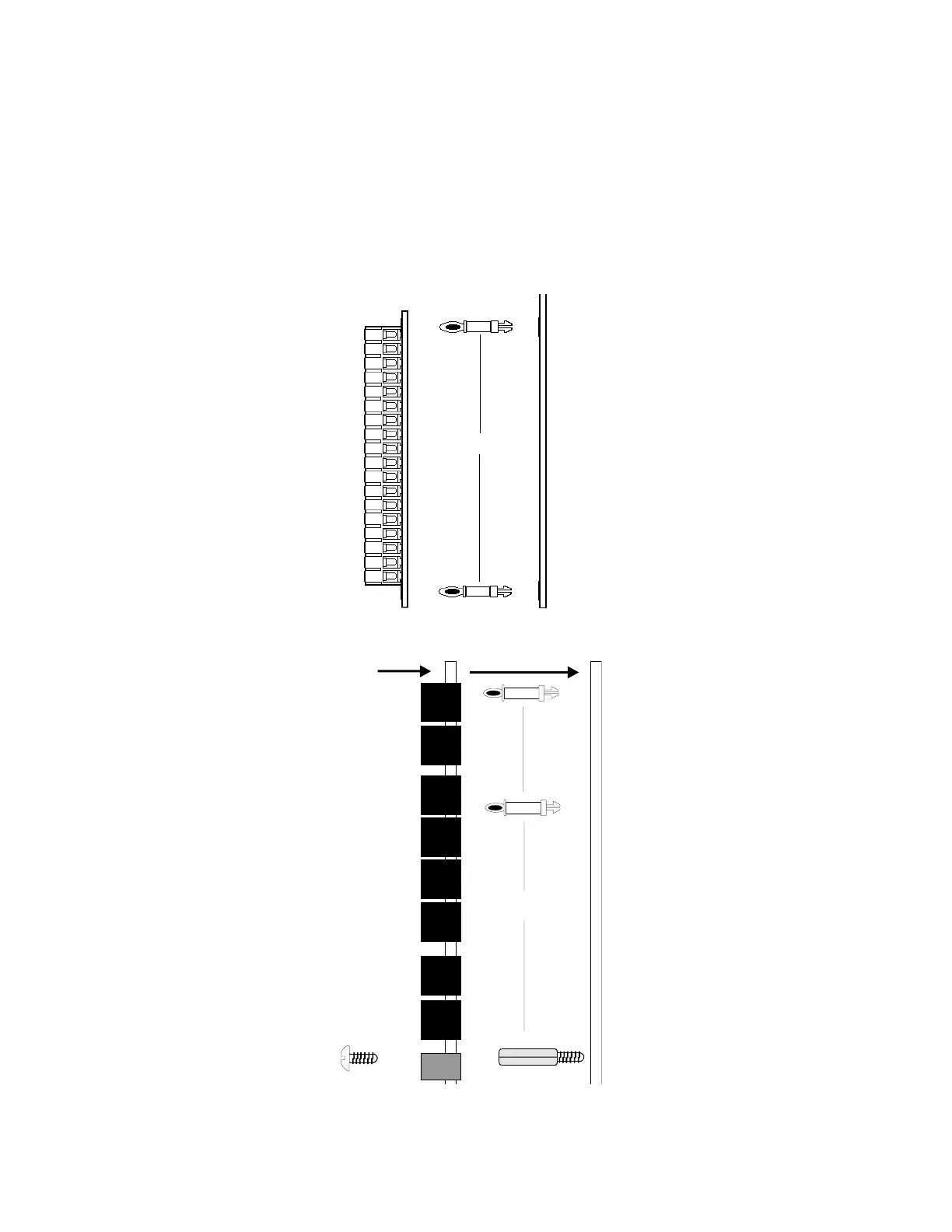
Insert the two nylon standoffs (provided) into the holes located on the right-side edge of the main circuit board
(refer to Figure 2-33). Carefully align the pins on the circuit board with the connector on the option board.
Press firmly on the option board until it locks in place on the standoffs. Affix the terminal identification labels
provided with the option modules.
For RTM-8 Option Module
Use the screw supplied to fasten the module to the main circuit board using the hole on the upper right-hand
corner of RTM-8 (when the board is in place for installation) and the corresponding hole on the main circuit
board.
Standoffs
4XTM Option Board Main Board
RTM-8 Option Board
Insert screw here
Standoffs
Main Board
Use metal screw and
standoff here
Figure 2-33 Optional Module Installation
2.7.6 Optional Modules, continued