EasyManuals Logo

Notifier AFP-200 User Manual

Notifier AFP-200
120 pages
To Next Page IconTo Next Page
To Previous Page IconTo Previous Page
Page #47 background imageLoading...
Page #47 background image
AFP-200 Instruction PN 15511:F2 10/11/99 47
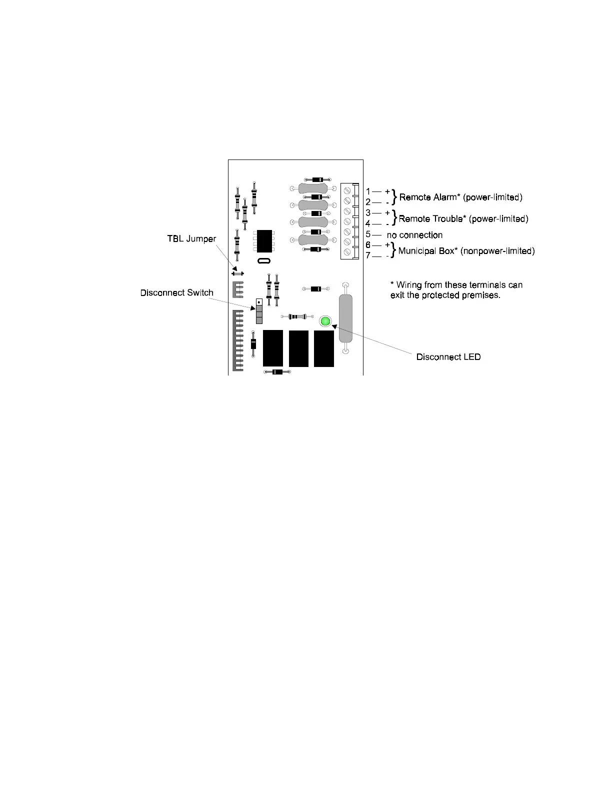
Figure 2-34 4XTM Transmitter Module
(Polarities are shown in activated positions.)
Push the disconnect switch down to prevent unwanted activation of the municipal box during testing of the
control panel (see Figure 2-34). The Disconnect LED will remain illuminated while the municipal box is
disconnected. The System Trouble LED will indicate disconnected and/or open circuit conditions on the
municipal box. During trouble conditions, it is possible to obtain the circuit condition on the alarm reverse-
polarity output. If this operation is desired, cut the TBL jumper (shown in Figure 2-34).
2.7.6 Optional Modules, continued

Other manuals for Notifier AFP-200

Questions and Answers:

Question and Answer IconNeed help?

Do you have a question about the Notifier AFP-200 and is the answer not in the manual?

Notifier AFP-200 Specifications

General IconGeneral
Control Panel TypeAddressable Fire Alarm Control Panel
Auxiliary Power Output24 VDC, 500 mA
Operating Temperature32°F to 120°F (0°C to 49°C)
Display80-character LCD
Power Supply120 VAC, 60 Hz
Capacity198 addressable devices
Notification Appliance Circuits2
Relay Contacts3 (Form-C)
Relative Humidity93% non-condensing

Related product manuals