Page 74 AFP-2800 - Fire Indicator Panel – Appendix
© N
OTIFIER
I
NERTIA
P
TY
L
TD
, 2001
WWW
.
INERTIA
.
COM
.
AU
5.8.1.4
5.8.1.45.8.1.4
5.8.1.4 M
MM
M
AIN
AIN AIN
AIN
T
TT
T
ERMINATION
ERMINATION ERMINATION
ERMINATION
B
BB
B
OARD
OARD OARD
OARD
- C
- C- C
- C
ONNECTING
ONNECTING ONNECTING
ONNECTING
R
RR
R
ELAY
ELAY ELAY
ELAY
O
OO
O
UTPUTS
UTPUTSUTPUTS
UTPUTS
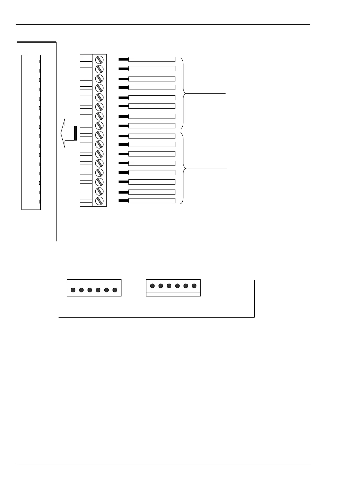
MONITORED OUTPUTS
STD N/O RELAY OUTPUTS
BELL OUTPUT
WARNING SYSTEM OUTPUT
OUTPUT 4
OUTPUT 3
GENERAL ALARM CONTACT
OUTPUT 6
OUTPUT 7
OUTPUT 8
+OP5
-OP5
+OP6
-OP6
+OP7
-OP7
+OP8
-OP8
+OP1
-OP1
+OP2
-OP2
+OP3
-OP3
+OP4
-OP4
TERM 8
5.8.1.5
5.8.1.55.8.1.5
5.8.1.5 M
MM
M
AIN
AIN AIN
AIN
T
TT
T
ERMINATION
ERMINATION ERMINATION
ERMINATION
B
BB
B
OARD
OARD OARD
OARD
- P
- P- P
- P
ANEL
ANEL ANEL
ANEL
E
EE
E
XPANSION
XPANSION XPANSION
XPANSION
R
RR
R
ELAY
ELAYELAY
ELAYS
SS
S
Note that the Panel Expansion Relay boards must be connected in a closed serial loop between
J16 and J14 on the Main Termination Board for the software to auto-detect the actual number of
Relay boards connected. The maximum allowed is 8 x 8 way relays boards. If the serial loop is left
open, the panel will assume that all 8 boards are present.
Note: If no expansion relay boards are used, jumper pins J18, situated close to the J14 connector,
must be shorted togther.
To First Relay Board
J16
From Last Relay Board
PIN 1
HEADER J16
Pin1 = VCC
Pin 2 = GND
Pin 3 = 24V
Pin 4 = STROBE2
Pin 5 = DATA OUT
Pin 6 = CLOCK
Main Termination Board
HEADER J14
Pin1 = VCC
Pin 2 = GND
Pin 3 = 24V
Pin 4 = STROBE2
Pin 5 = DATA IN
Pin 6 = CLOCK
J14
PIN 1
www.PDF-Zoo.com

 Loading...


