P
AGE
90 AFP-2800 - F
IRE
I
NDICATOR
P
ANEL
– A
PPENDIX
N
OTIFIER
I
NERTIA
P
TY
L
TD
(ABN 076 002 692 962)C
OPYRIGHT
© 2001
WWW
.
INERTIA
.
COM
.
AU
5
55
5
5
55
5
.
..
.
.
..
.
1
11
1
1
11
1
2
22
2
2
22
2
.
..
.
.
..
.
6
66
6
6
66
6
L
LL
L
L
LL
L
C
CC
C
C
CC
C
D
DD
D
D
DD
D
-
--
-
-
--
-
8
88
8
8
88
8
0
00
0
0
00
0
D
DD
D
D
DD
D
I
II
I
I
II
I
S
SS
S
S
SS
S
P
PP
P
P
PP
P
L
LL
L
L
LL
L
A
AA
A
A
AA
A
Y
YY
Y
Y
YY
Y
I
II
I
I
II
I
N
NN
N
N
NN
N
T
TT
T
T
TT
T
E
EE
E
E
EE
E
R
RR
R
R
RR
R
F
FF
F
F
FF
F
A
AA
A
A
AA
A
C
CC
C
C
CC
C
E
EE
E
E
EE
E
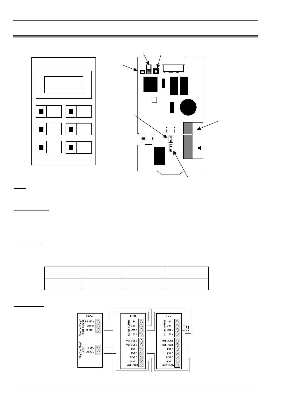
Note:
Both Operating Mode switches (SW4 & SW5) on the PCB must be set for ACS Mode (the UP position).
Event sounder:
Setting DIP Switch 1 of SW1 to OFF will disable the buzzer for alarms. Setting DIP Switch 2 of SW1 to OFF will
disable the buzzer for faults. If the buzzer is enabled, pressing the “MUTE” button will silence the buzzer until a
new event is received.
Addressing:
SW2 & SW3 set the address as per the table below. Note that “200” is added to the actual values of SW2 & SW3
to give an address in the range 200 – 229.
SW3-1 SW3-2 SW2 Actual Address
OFF OFF 0 – 9 200 – 209
ON OFF 0 – 9 210 – 219
ON ON 0 – 9 220 - 229
Connections:
RS485 Comms
connector (see
diagram below)
24V Power
connector (see
diagram below)
SW3
SW2SW1
SW4
SW5
Display
Isolates
Display
Alarms
Display
Faults
Next
Previous
Mute
10 SEPT 12:34 1/1
EAST WING
1.2.Z6 FAULT
A=0 F=1 I=0
www.PDF-Zoo.com
 Loading...


