Appendix
116 AFP-2800/2802 Manual – P/N 11249 11-Mar-08
8.7.4.2 ANALOG LOOP INSTALLATION CHECKS AND FAULT FINDING
Before connecting a loop to an LCM or LEM card, carry out the following tests:
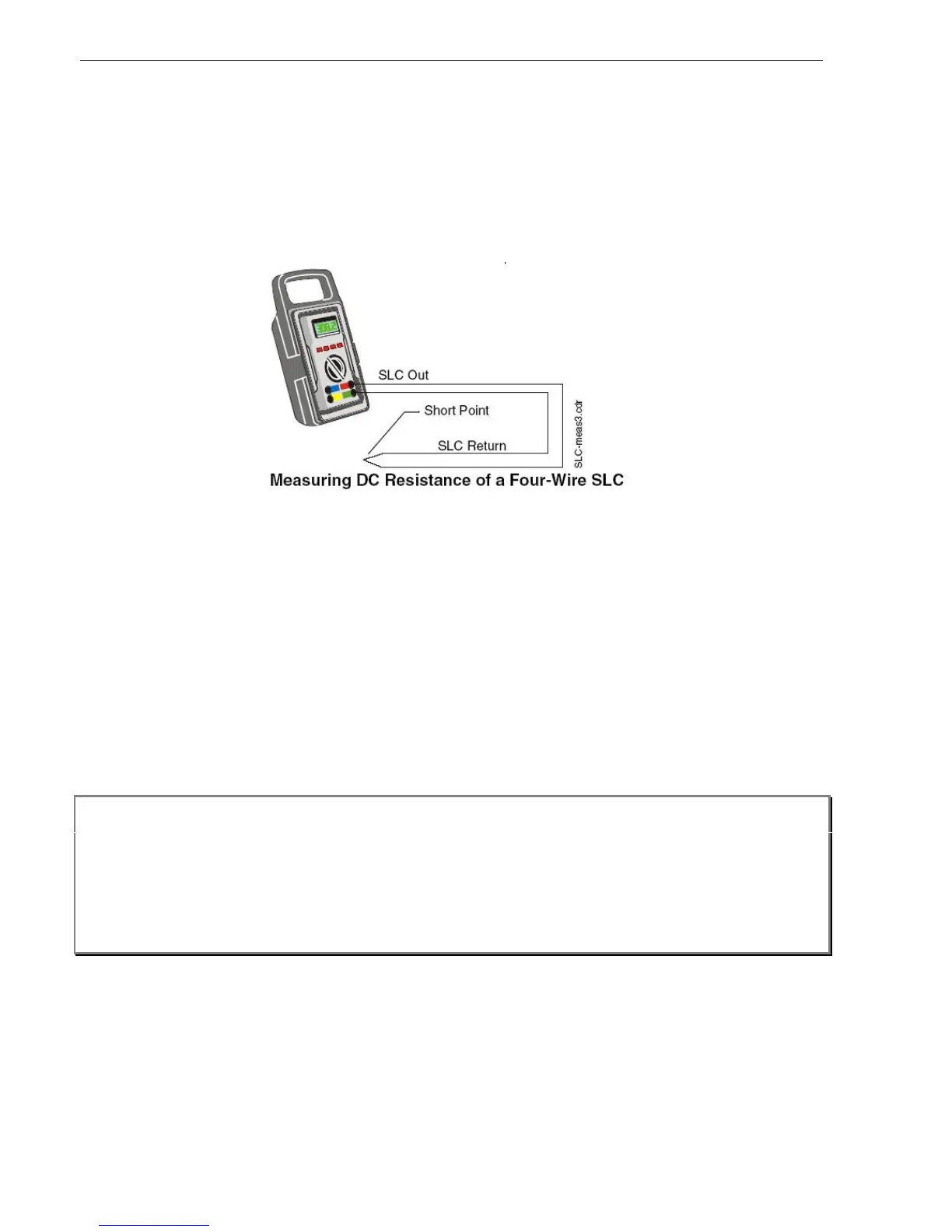
1. Check loop continuity and resistance by placing a short circuit on one end of the loop and reading the loop
resistance with a multimeter at the other (be sure to set the multimeter to Ohms). The loop resistance cannot
exceed 50 Ohms which is 25 Ω per leg. Refer to note below if using ISO-X modules.
2. Check devices for correct wiring as follows. With both ends of the circuit open, set the multimeter to diode
test, and place the leads on the cable, the reading should be approx. 0.645, reverse the leads to get a reading
of approximately 1.2 or higher. If both readings are low, there is an incorrectly wired device, or a short on the
wiring. (Note: Each device has a diode installed)
3. Check the loop voltage as follows. Set the multimeter to D.C. volts and read the voltage at the loop card
before connecting the loop. The reading should be 24 – 25 volts. Now connect the loop. The reading should
be 15-16 volts. If the measured voltage goes below this value, there could either be a short on the line or a
device may be incorrectly wired (possible reverse polarity). Find the device and correct the loop connections
at that device.
4. Check that there are no earth faults as follows. Select ohms on the multimeter and measure between each leg
of the loop and earth. If the reading falls below 50,000 Ω, an earth fault will be indicated when the loop is
connected. Find the cause of the earth fault and rectify it. (Note: Possible causes of an earth fault are
moisture, inadequate insulation from the surrounding building, equipment or materials).
NOTE:
Loop resistance measurement when ISO-X isolation modules are present:
When power is removed from the loop, the positive side of the circuit is opened at each ISO-X
isolation module. To measure the loop resistance, temporarily place a jumper between Terminals 2
and 4 on each ISO-X while taking measurements. Remember to remove all the jumpers and test all
isolator modules when you have finished taking the readings.
Refer to SLC Wiring Manual for more information.