AFP-3030 Operations Manual — P/N DOC-01-039:A 26/11/2015 62
Installed Points Report Screen Printing Reports
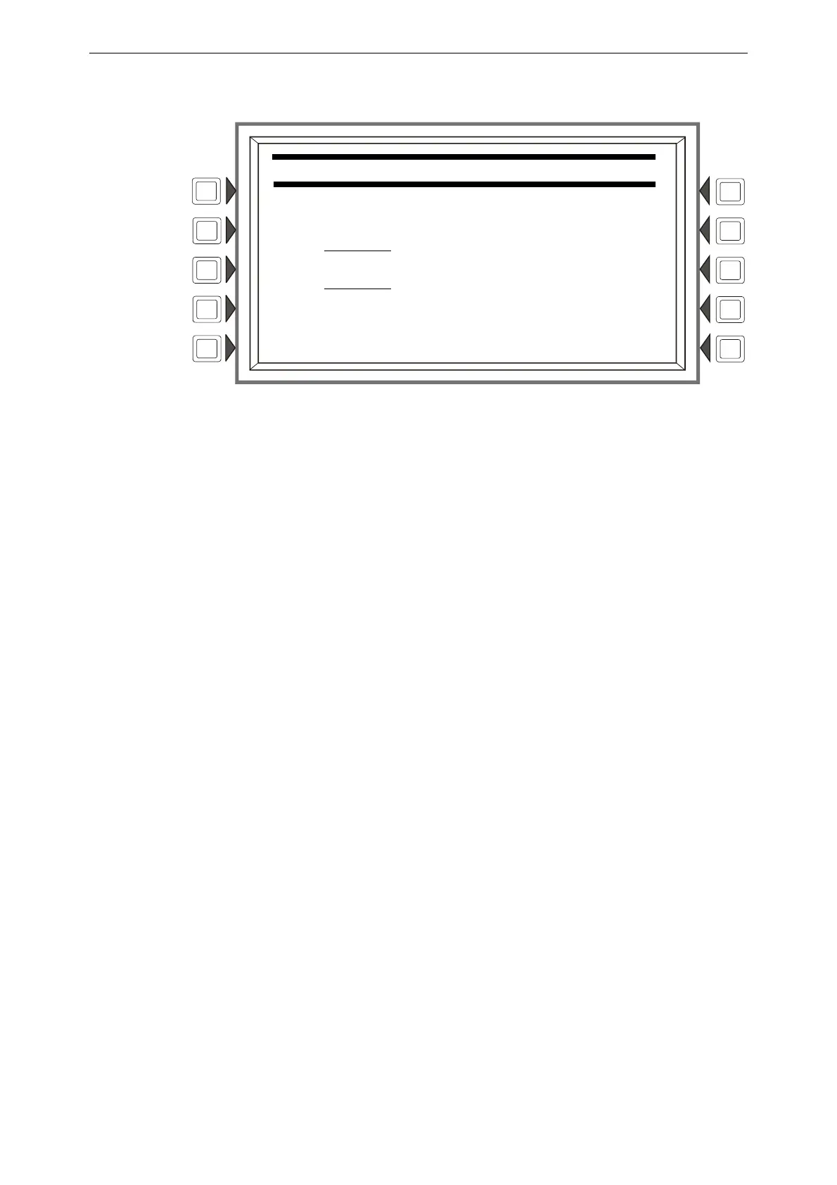
RANGE: Press to bring up the following screen, which allows the programmer to choose a range of
installed points to print.
Figure 5.6 Installed Points Menu - Range
Soft Keys
START POINT: Press to place the cursor in this field, and to toggle between the choices, which
appear in print order: DETECTOR (loop1, detector 1 through loop 10, detector 159), MODULE
(loop 1, module 1 through loop 10, module 159), GENERAL ZONE, LOGIC ZONE, RELEASE
ZONE, ACS PTS, SPECIAL ZONE, FAULT ZONE. Using the keypad, type in the start point
address.
END POINT: Press to place cursor in this field, and to toggle between the choices as described
above. Using the keypad, type in the end point address.
INSTALLED POINTS MENU
START POINT:
LO1D001 (DETECTOR)
END POINT:
ZT10 _ (FAULT ZONE)