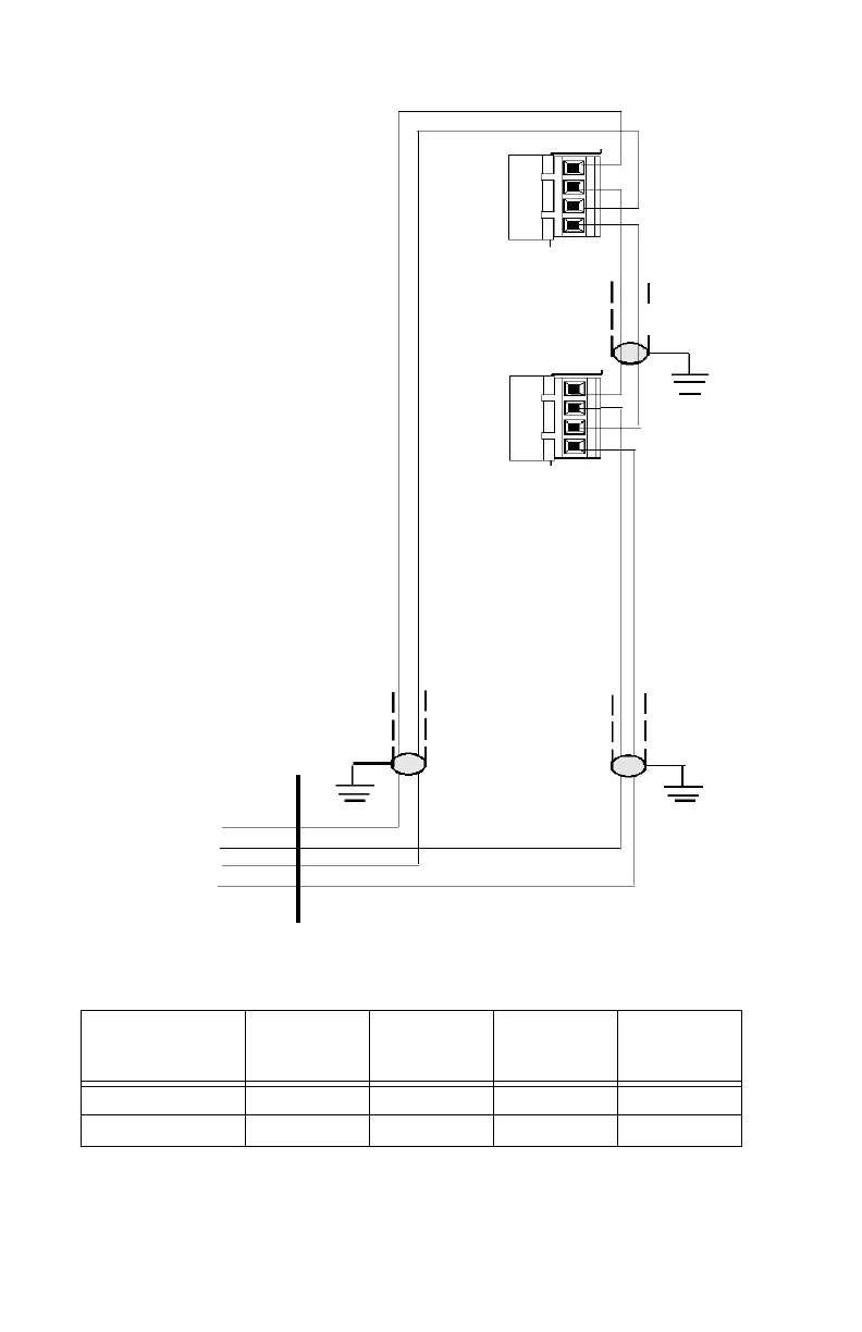
Terminal Mode Configuration Terminal Mode EIA-485 Connections
14 LCD2-80 Instruction Manual — P/N 53242:B1 10/25/2012
Figure 2.2 Terminal Mode EIA-485 Connections
Last LCD2-80
(must set DIP Switch
SW3-7 and SW3-8
“ON” and SW3-5 “ON”)
All LCD2-80s except
last one
(set DIP Switch SW3-7
and SW3-8 “ON” and
SW3-5 “OFF”)
TB2
TB2
Twisted-
Shielded Pairs
EIA-485
Return
EIA-485
Out (-)
Return (-)
Out (+)
Return (+)
EIA-485
Out
Cabinet
*See notes in preceding text.
4
3
2
1
4
3
2
1
EIA-485
Connections on
LCD2-80
OUT(-) RET(-) OUT(+) RET(+)
NFS-320, NFS2-640 TB11-2 TB11-4 TB11-1 TB11-3
NFS2-3030, NCA-2 TB9-2 TB9-4 TB9-1 TB9-3
Table 2.1 EIA-485 Control Panel Connections (Terminal Mode)