Connections Product Overview
LCD2-80 Instruction Manual — P/N 53242:B1 10/25/2012 9
1.5 Connections
1.5.1 Terminal Connections - TB1 and TB2
These connections provide 24 VDC operating power (TB1) and EIA-485
connections (TB2) to the LCD2-80.
The connections must be power-limited.
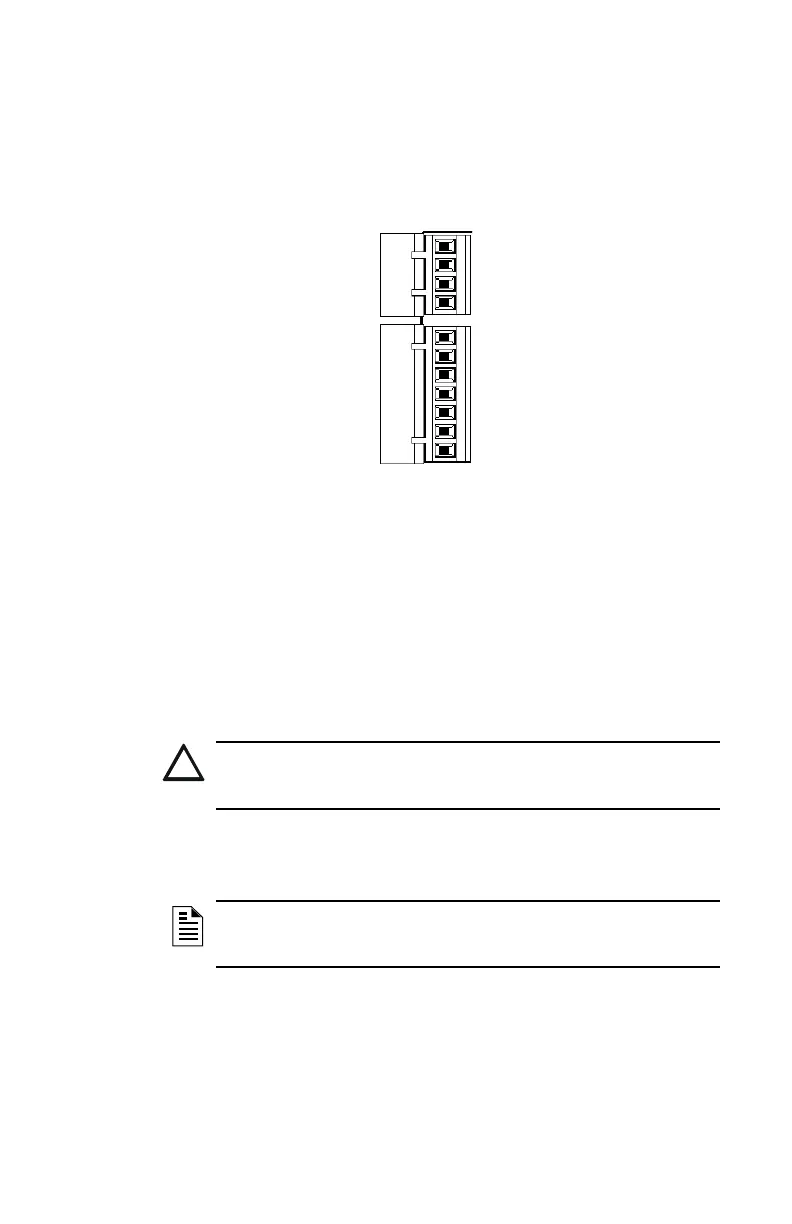
Power connections are illustrated below. Refer to “Terminal Mode EIA-
485 Connections” on page 13 and “ACS Mode EIA-485 Connections”
on page 16 for TB2 connection illustrations.
Power Connections (TB1)
The LCD2-80 can be powered by a +24 VDC power supply listed for fire
protective signalling use that is power limited and regulated with a voltage
range of +17 VDC to +28 VDC. Power can also be provided by an FACP
with an integral power supply as long as the LCD2-80 is listed for use
with the FACP.
The power run to the LCD2-80 must be power-limited but need not
contain a Power Supervision Relay since loss of power is inherently
supervised through communication loss.
-EIA-485 In
-EIA-485 Out
+EIA-485 In
+EIA-485 Out
No connection
Reference
-Common Out
-Common In
+24 Volts Out
+24 Volts In
No connection
TB1
TB2
Figure 1.2 TB1, TB2 Connections
CAUTION:Risk of Equipment Damage!
Do not power the LCD2-80 from any unfiltered power source designed
for powering NAC devices. This may damage the equipment.
NOTE:If the LCD2-80 is powered from a separate supply from the
control panels, the suppyling commons should be tied together and
ground fault detection should be disabled in all but the primary supply.