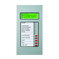
Product Overview Switches and Indicators
10 LCD2-80 Instruction Manual — P/N 53242:B1 10/25/2012
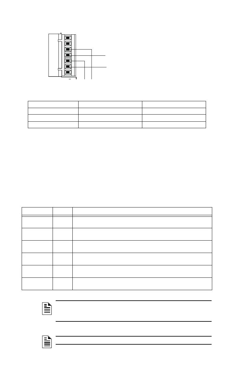
Figure 1.3 Supplying Power to the LCD2-80
1.5.2 NUP Connection - J3
Connection for standard NUP cable for VeriFire
®
Tools downloads.
1.5.3 AKS-1B Keyswitch - J2
Keyswitch connector for an optional AKS-1B keyswitch. When the two
pins on this interface are shorted, all five keys on the membrane panel will
be ignored by the LCD2-80.
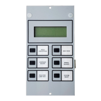
1.6 Switches and Indicators
1.6.1 LED Indicators
24 VDC (+) Common (-)
FCPS-24S6/8 TB4-9 TB4-10
NFS-320, NFS2-640
TB10 Nonresettable 24VDC+ TB10 Nonresettable 24VDC-
NFS2-3030, NCA-2 TB6+ TB6-
7
6
5
4
3
2
1
TB1
From Main Power Supply
(-) Common
(+) 24 VDC Power
(+) (-) To next LCD2-80
LCD2-80
LED Color Function
Alarm Red Indicates an Alarm condition on the FACP. This LED will remain lit until all
alarm conditions have been cleared.
Supervisory Yellow Indicates a Supervisory condition on the FACP. This LED will remain lit until
all supervisory conditions have been cleared.
System
Trouble
Yellow Indicates a Trouble condition on the FACP. This LED will remain lit until all
trouble conditions have been cleared.
Point Disable Yellow Indicates that a point on the FACP has been disabled. This LED will remain
lit until the point has been re-enabled.
Signal
Silence
Yellow Indicates that any or all silenceable outputs have been silenced. This LED will
be lit until the outputs have resounded or a reset is performed on the FACP.
Other Yellow Indicates that an Other or Security event has occurred on the FACP. This
LED will remain lit until all other and security events have been cleared.
Table 1.1 LED Functions
NOTE: The LEDs operate in Terminal mode only when used with the NFS-
320, NFS2-640, and NFS2-3030/NCA-2. They do not activate for off-normal
events from legacy panels in Terminal mode.
NOTE:The second and eighth LEDs are reserved for Future Use.