Do you have a question about the Notifier LCD2-80 and is the answer not in the manual?
Emphasizes the critical role of ongoing maintenance for fire alarm system reliability.
Details critical warnings regarding power disconnection and safe servicing procedures to prevent damage.
Covers re-acceptance testing requirements and environmental operating conditions for the system.
Details UL 864 compliance and products requiring Authority Having Jurisdiction (AHJ) approval.
Lists programmable features and options that need local AHJ approval for compliance.
Provides a diagram identifying key components and connection points on the LCD2-80 board.
Details the current consumption of the LCD2-80 under various operating conditions for power supply calculations.
Explains the purpose and requirements for TB1 (power) and TB2 (EIA-485) terminal connections.
Specifies acceptable power sources and critical warnings regarding equipment damage from incorrect power.
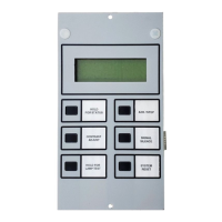
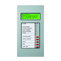
Details the function, color, and meaning of each LED indicator on the LCD2-80.
Provides a comprehensive guide to setting each DIP switch for various functions and modes.
Describes how the LCD2-80 functions as a CRT terminal and notes placement requirements.
Details the specific settings for DIP switches (SW3) and the ACS/TERM switch (SW10) for Terminal Mode.
Lists essential requirements for EIA-485 connections in Terminal Mode, including power, distance, and cable type.
Illustrates the EIA-485 wiring for multiple LCD2-80 units in Terminal Mode.
Details the necessary settings for DIP switches (SW3), ACS/TERM switch (SW10), and address switches for ACS Mode.
Explains how to program the LCD2-80 using VeriFire® Tools, including download procedures.