30 NFS2-640/E Installation Manual — P/N 52741:P2 7/10/14
Installation Mounting Option Boards
3.6.4 Transmitter Module TM-4
TM-4 is power-limited. Connections are on TB10 nonresettable output and TB11 EIA-485 ACS
Mode. Refer to the Transmitter Module TM-4 installation document for installation details.
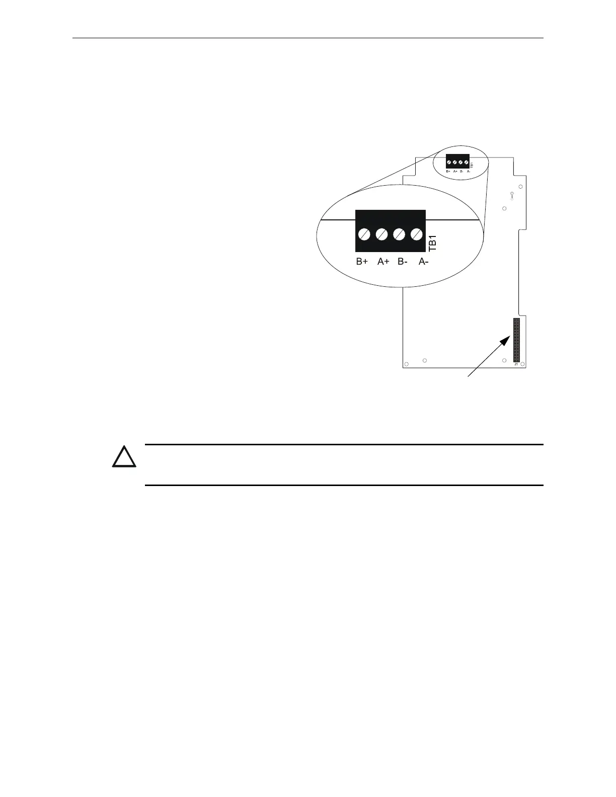
3.6.5 Loop Expander Module
Installing a Loop Expander Module
adds a second SLC loop to the control
panel. Refer to Figure 3.12 for stacker-
connector illustrations.
1. Plug short end of the stacker-
connector into J4 on the CPU2-
640.
2. Align the LEM with the four
1 inch standoffs and the stacker-
connector as shown in
Figure 3.12; firmly seat the
stacker-connector.
3. Attach LEM to standoffs using
screws or another set of standoffs.
4. After LEM is mounted on the
control panel, connect the SLC
loops to TB1 on the LEM and
TB13 on the CPU2-640. This
system supports either FlashScan
or CLIP mode devices. Refer to
the SLC loop manual for wiring
requirements and specific details.
LEM-SLC.wmf
Figure 3.11 SLC Connections for LEM-320
Attach stacker-connector to CPU as
shown in Figure 3.12.
CAUTION:
For the SLC to function correctly, the stacker-connector must be installed as shown in Figure 3.12.
Do not install other option modules on top of the LEM-320.