NFS2-640/E Installation Manual — P/N 52741:P2 7/10/14 57
Releasing Applications Applications
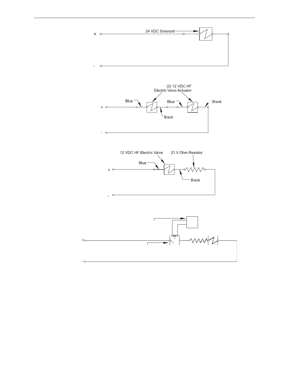
Figure 4.8 Releasing Circuits (Option 1)
Figure 4.9 Releasing Circuits (Option 2)
Figure 4.10 Releasing Circuits (Option 3)
)
Figure 4.11 Release Circuits (Mechanical Disconnect Switch)
4.7.4 Connecting a Releasing Device to the FCM-1 Module
The module can control 1 A of current. Make sure to keep total system current within the limits of
the power supply. You can power the module from the power supply of the Control Panel or any
UL/ULC listed 24 VDC regulated power-limited power supply for Fire Protective Signaling. For
more information, refer to the Device Compatibility Document.
GasDisconnectMod.wmf
Mechanical Disconnect Switch listed for the application
Note: Disconnect switch must provide separate dry
contacts to indicate supervisory.
Monitor Module