NFS2-640/E Installation Manual — P/N 52741:P2 7/10/14 33
Connecting the Power Cables Installation
Wire and fiber, or multi-mode and single-mode, can be mixed.
3.7 Connecting the Power Cables
3.7.1 Overview
Complete all mounting procedures and check all wiring before applying power. Electrical
connections include the following:
• Primary AC power source – 120 VAC, 50/60 Hz, 5.0 A (with NFS2-640E use 240 VAC,
50/60 Hz, 2.5 A) from line voltage source. Overcurrent protection for this circuit must comply
with Article 760 of the National Electrical Code (NEC) and/or local codes. Use 12 AWG (3.31
mm
2
) wire (maximum) with a 600-volt rating.
• Secondary power source – 24 VDC from batteries, installed in the control panel (or in an
optional battery cabinet). Secondary (battery) power is required to support the system during
loss of primary power.
• External power sources – 24 VDC power for Smoke Detectors (4 wire), NACs, and
Annunciators.
• Auxiliary power source – 24 VDC power @ 0.5 A and 5 VDC power @ 0.15 A from TB2 on
the CPS-24/E.
See Appendix B.1 “Electrical Specifications” for details and overall installation guidelines.
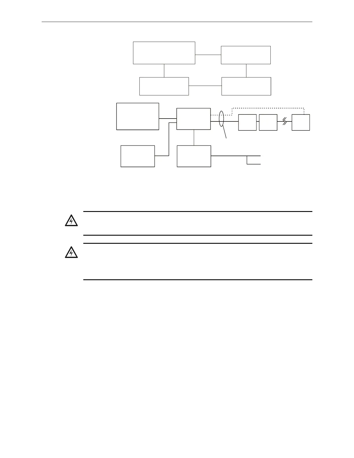
Low level analog audio
NUP
AA Series Audio Amplifiers
XPIQ, etc.
With DVC and
DVC-AO for
retrofits. DAL
(Digital Audio
Loop) not
compatible
with this
application.
With DVC,
NCA-2,
DAL, and
DVC-AO
for retrofits.
Figure 3.13 Block Diagrams of DVC Series Applications
2-640DV1.wmf
2-640DV2.wmf
DVC
NFS2-640
NCA-2
DAL
Device
DAL
Device
DAL
Device
NUP
SLC
Low level
analog audio
NFS2-640
DVC
XPIQ
DVC-AO
DVC-AO
WARNING:
Remove all power sources to equipment while connecting electrical components. Leave the
external, main power breaker OFF until installation of the entire system is complete.
WARNING:
Several sources of power can be connected to the control panel. Before servicing the control panel,
disconnect all sources of input power including the battery. While energized, the control panel and
associated equipment can be damaged by removing and/or inserting cards, modules, or
interconnecting cables.