35
ML0044B December 1, 2017 Copyright 2016 Bitronics, LLC
3.0 CONNECTIONS & WIRING
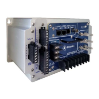
The connection view of the PPX II is shown in figure 3.
See Appendix A1 for detailed wiring diagrams covering the CT/VT measurement
inputs.
3.1 Auxiliary Power
The PPX II is powered by connections to L1(+) and L2(-). A green LED Power (PWR)
indicator is provided on the front panel to indicate that the unit is powered ON.
3.1.1 Specifications (per section 1.3)
Power Supply Input (Auxiliary) Voltage – terminals L1(+) and L2(-)
DC PWR (Low Voltage Vdc) - Power Supply Input (Auxiliary Voltage - intended for
connection to 12V or 24V battery voltages)
Nominal: 12-40V dc
Operating Range: 8-40V dc
Burden: 5W max
Overcurrent protection (Required) : Refer to section 2.4
AUX PWR (Universal) - Power Supply Input (Auxiliary Voltage)
Nominal: 48-250V dc, 69-240V ac (50/60Hz)
Operating Range: 37-300V dc, 55-275V ac (45-65Hz)
Burden: 8W max, 24VA max
Overcurrent protection (Required) : Refer to section 2.4