OPERATION 10. HOW TO USE APPLIED FUNCTIONS (OPERATION MODE)
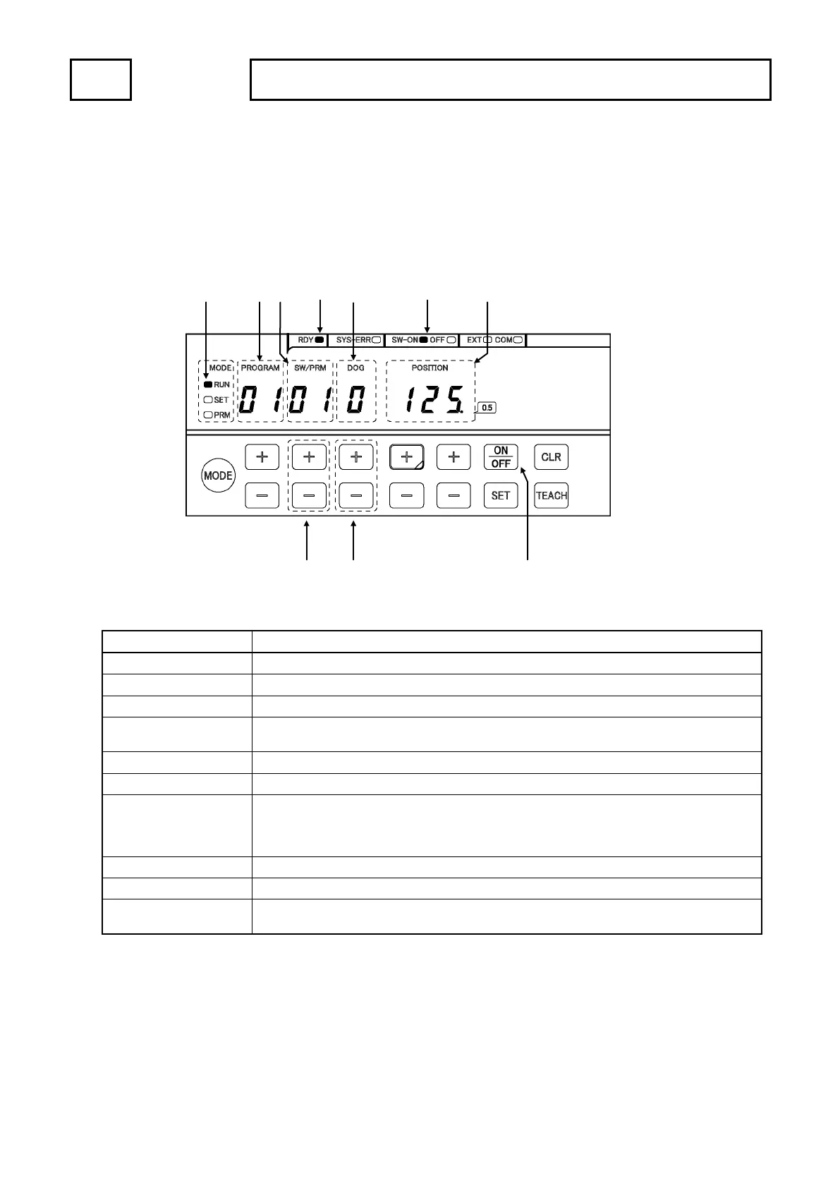
(2) Monitoring the setting value of the switch output
Setting values of the switch outputs which are registered programs during the operation can be checked.
Name Descriptions
①
Selects the switch number of the setting value which needs to check.
② DOG key Selects the dog number of the setting value which needs to check.
③ ON / OFF key Switches the ON and OFF setting value displays.
④ PROGRAM display
Displays selecting the program number.
(VS-5F and VS-5F-1 are not available this function.)
⑤
Displays the switch number.
⑥
⑦ ON / OFF indicator Indicates contents of the POSITION display area.
SW-ON LED is ON: Displays the ON setting value.
OFF LED is ON: Displays the OFF setting value.
⑧ POSITION display Displays the ON or OFF setting value.
⑨ MODE indicator RUN LED is ON: Indicates the operation (RUN) mode.
⑩
If there is no error, this indicator will turn ON when selecting the operation (RUN) mode.
This indicator is same condition as “System ready output signal” of the output connector.
⑨
④
⑤
⑩
⑥
⑦
⑧
①
②
③
 Loading...