OPERATION 10. HOW TO USE APPLIED FUNCTIONS (OPERATION MODE)
(3) Monitoring the ON / OFF state of the switch output
The ON / OFF state of the switch outputs which are registered programs during the operation can be checked.
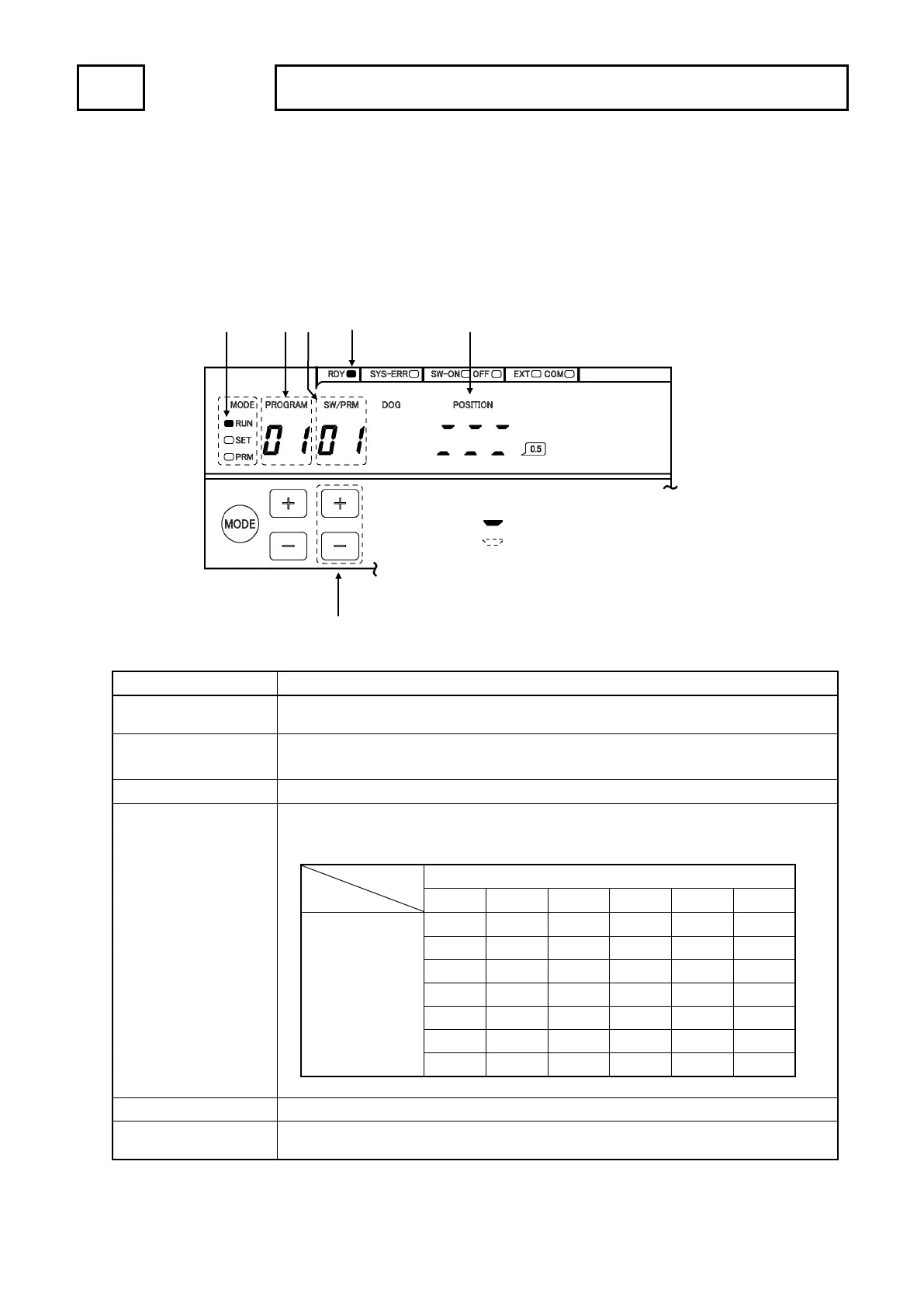
① PROGRAM display
Displays selecting the program number.
(VS-5F and VS-5F-1 are not available this function.)
② SW / PRM key ON / OFF state is displayed per six switches, and selects first switch number.
First switch No.: 01, 07, 13, 19, 25, 31, 37
③ SW / PRM display Displays the switch number.
④ POSITION display Indicates the ON / OFF state of the switch output.
ON / OFF state is displayed per six switches.
⑤ MODE indicator RUN LED is ON: Indicates the operation (RUN) mode.
⑥
If there is no error, this indicator will turn ON when selecting the operation (RUN) mode.
This indicator is same condition as “System ready output signal” of the output connector.
⑤
①
③
⑥
④
②
a b c
d e f
ON : (LED is ON)
:
Display of 7segment LED
a b c d e f
Applicable
switch No.
SW19 SW20 SW21 SW22 SW23 SW24
SW25 SW26 SW27 SW28 SW29 SW30
SW31 SW32 SW33 SW34 SW35 SW36
SW37 SW38 SW39 SW40 - -
 Loading...