Page 19 of 54
d) The potentiometer measuring the diameter gauge is connected from points J85 to J8-8. When
exchanging please make sure that the potentiometer is turned anticlockwise before fitting.
Important: the end of the gauge should be resting on the top of the main shaft housing during
replacement to allow minimum and maximum measurements to take place for all types of wheel
The contact no. 1 on the potentiometer take the white coloured wire and no. 2 the green wire, with
no. 3 taking the brown wire.
Contact Colour 1 ws 2 gn 3 bn
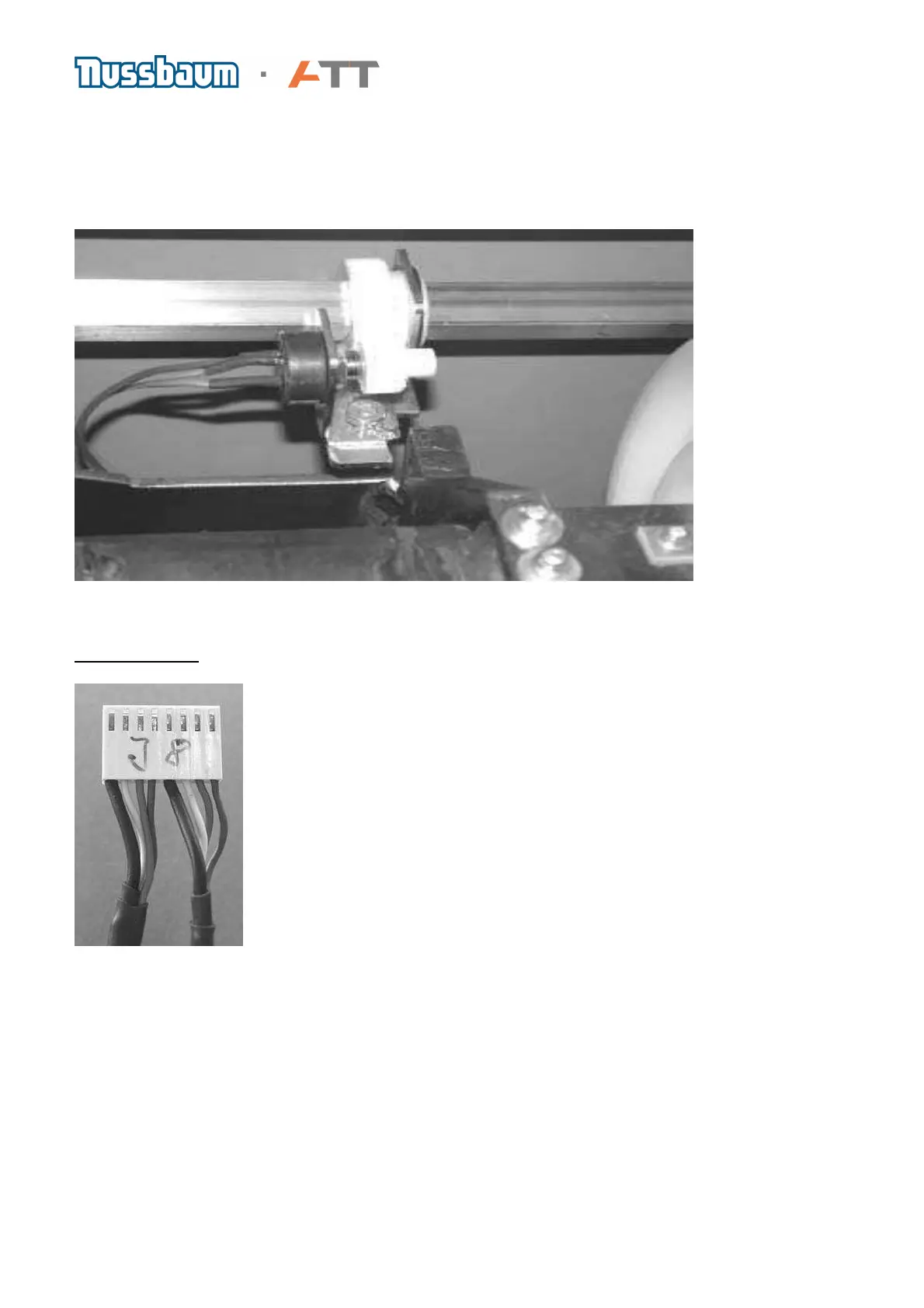
The photo shows connection plug J8. Connected to it are the leads from Potentiometer P1 for the
distance gauge (right side)and P2 for the wheel diameter (left side from BM 20 upwards) The
colour code order of wires on P2 is black, white, green and brown. For P1 on the other side is also
black, white, green and brown.
 Loading...