Page 20 of 54
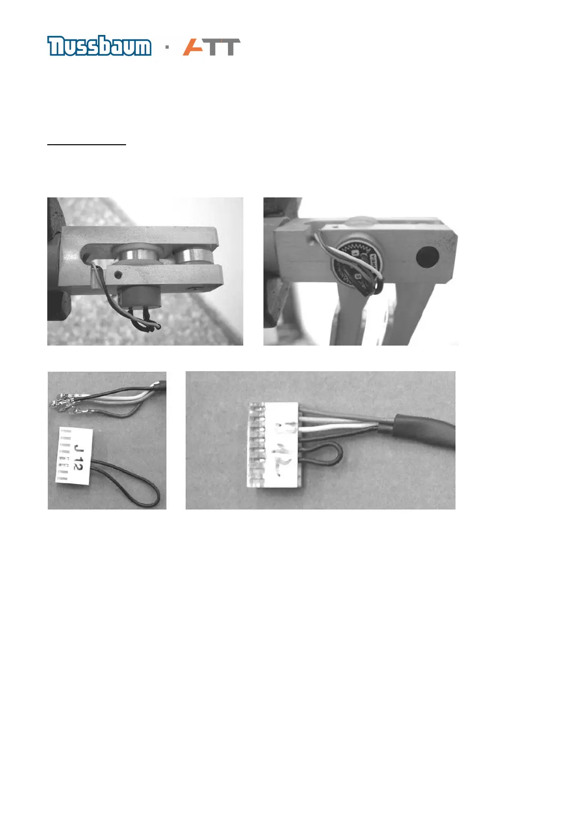
e) The potentiometer for the width (outside arm) is connected to J12-1 to J12-4. In order to
exchange the potentiometer these wires should be soldered onto the new one.
The contact no. 1 on the potentiometer take the white coloured wire and no. 2 the green wire, with
no. 3 taking the brown wire.
Contact Colour 1 ws 2 gn 3 bn
The reason why the wires need to be soldered is that the plug for the basic board cannot be
passed through the tube of the wheel guard and so it has to be removed.
The photos show the position of the potentiometers for the outside arm
The left photo shows the plug J12, which takes the leads coming from the outside gauge. On the
right shows the leads, soldered onto the plug in the order brown, green white and black.
 Loading...