INSTALLATION, USE & CARE INSTRUCTIONS
INSTALLATION, OPERATION
13
WIRING
WARNING
Risk of electric shock. Electrical wiring must be
done by qualified personnel in accordance with all
applicable codes and standards. Before connecting
wires, switch power off at service panel and lock
service disconnecting means to prevent power from
being switched on accidentally.
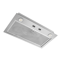
1. Using appropriate wire nuts (not included), connect house
power cable to unit wiring: BLACK to BLACK, WHITE to
both WHITE wires and GREEN or bare wire to GREEN
ground screw (FIG. 20).
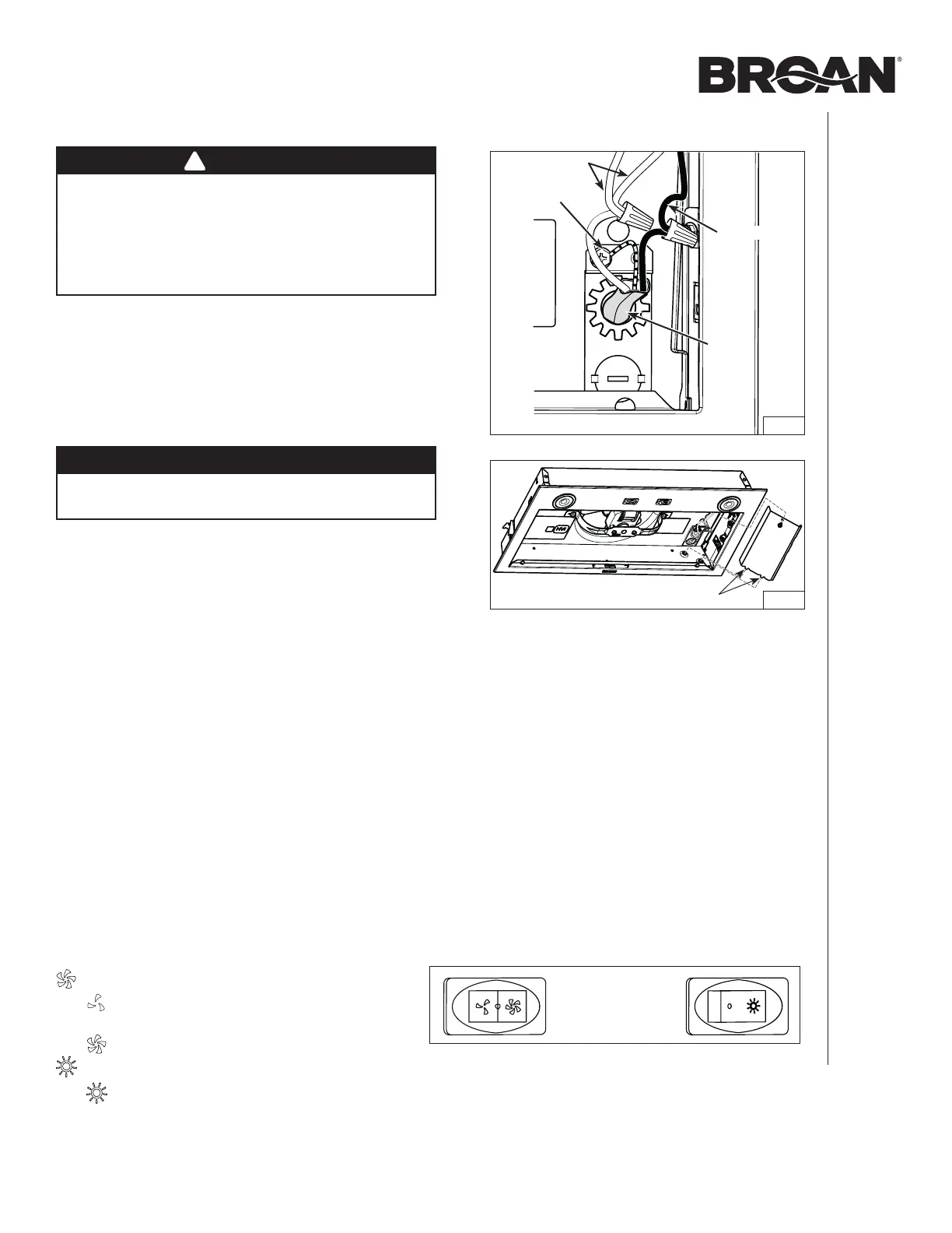
2. Reinstall the wiring compartment cover in the unit; ensuring
the bottom tabs are inserted in their embossed location.
Secure in place using its retaining screw (FIG. 21).
CAUTION
Take care not to pinch wires while reinstalling wiring
cover.
INSTALL THE FILTER(S)
Ducted Installation
Reinstall the grease filter(s).
Non-Ducted Installation
PM300SS unit only: Attach the non-ducted filter (included
with the HARKPM21 non-duct kit) to the back of the
grease filter using clips (provided with non-ducted filter).
To order a new non-ducted filter, use service part number
S99010464.
BBN1243SS and BBN1303SS units only: Attach
the non-ducted filters (included with the HARKBN24
or HARKBN30 non-duct kit) to the back of the grease
filters using clips (provided with non-ducted filters). To
order new non-ducted filters, use service part number
S99010464-124 for BBN1243SS and S99010464-130
for BBN1303SS model.
2 WHITE WIRES
BLACK WIRE
FIG. 20
GREEN
GROUND
SCREW
FIG. 21
TABS
OPERATION
Blower Switch:
Turns blower on to LOW speed.
o Turns blower OFF.
Turns blower on to HIGH speed.
Light Switch:
Turns light ON.
o Turns light OFF.
HOUSE
POWER
CABLE