MPC5746R Hardware Design Guide, Rev. 1
MPC5746R Package Options Overview
NXP Semiconductors2
of the reader. The Reference Manual, Data Sheet and Errata report are the official specifications for
MPC5746R and should be reviewed for the most up-to-date information available for this device.
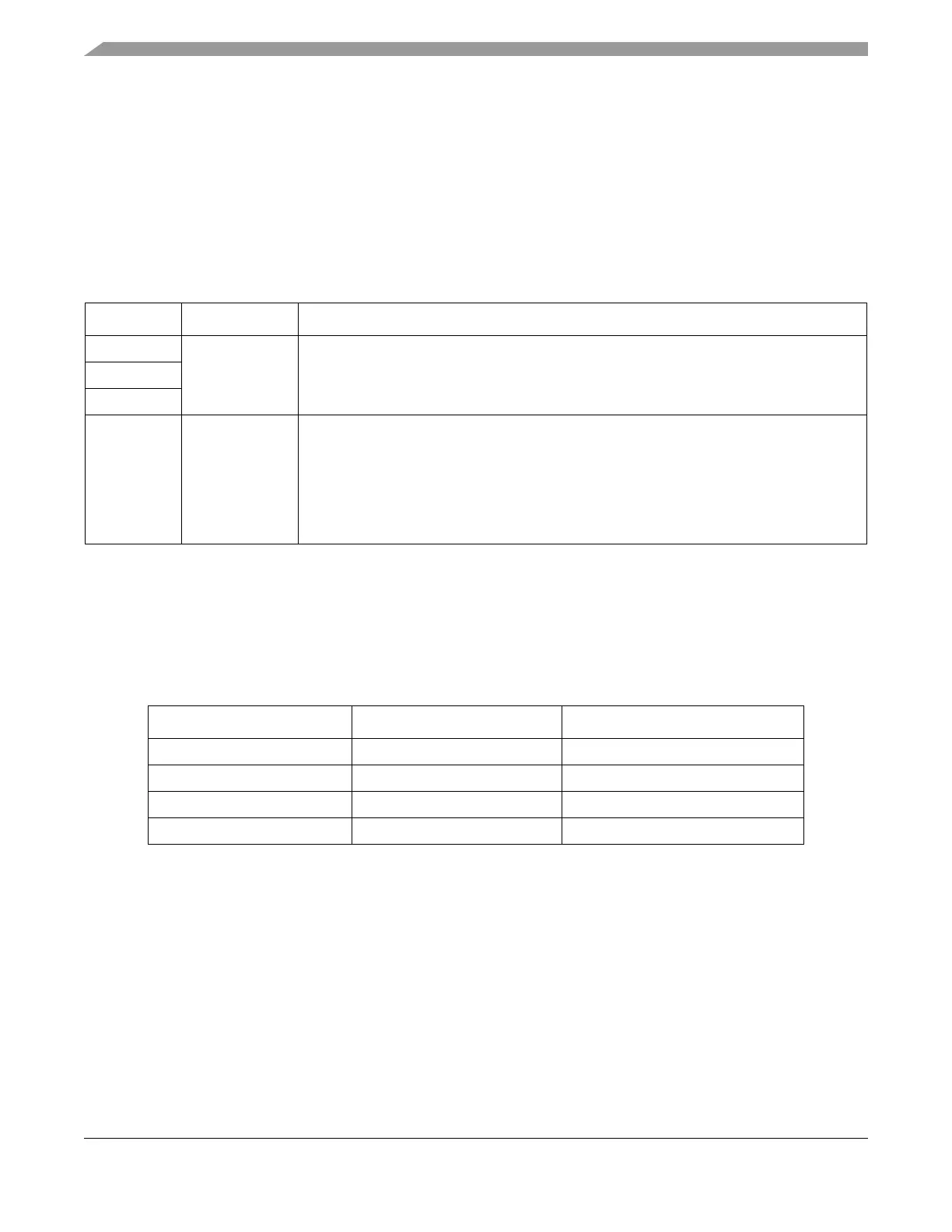
2 MPC5746R Package Options Overview
The MPC5746R is available in four different package options; three of these are intended for production
and one is intended to provide additional features to support debug and calibration.
The package selection should be based on the number of input/output pins required for the application and
the area available for the target system. The following table shows the sizes of different packages. See the
MPC5746R Data Sheet for complete package dimensions and ball placement. Drawings are also available
on the NXP web site; search for the case outline number shown in Table 2.
3 Power Supply
MPC5746R provides several options for providing power supply voltages. The main power supplies
required are 1.25 V, 5 V and 3.3 V depending on the requirements of the application. The on-chip flash
memory supply is generated internally. The SRAM has a separate supply input for data retention features,
if they are required.
In addition the MPC5746R microcontroller includes a robust power management infrastructure that
enables applications to select among various user modes and to monitor internal voltages for high- and
Table 1. MPC5746R Package Options
Package Target Description
144 LQFP
Production
Provides access to the primary features of the device. Packages with additional pins provide
additional features and/or additional GPIO. No Nexus High Speed Aurora Trace interface is
provided on any production package, only JTAG.
176 LQFP
252 MAPBGA
292 MAPBGA Development
Provides access to primary features of device, plus Nexus High Speed Aurora Trace and
overlay/trace memory that can be used for calibration. This package is designed for debug
and calibration development use and is typically provided mounted to an interposer/adapter
system to connect to either a 144LQFP, 176 LQFP or 252 MAPBGA footprint. The Aurora
debug interface connector is provided on this adapter board, eliminating the need for the
customer to route the high speed Aurora differential pairs and allowing use on the customer
PCB.
Table 2. Package Sizes
Package Physical Size (mm) Case Outline Number
144 LQFP 20 x 20 98ASS23177W
176 LQFP 24 x 24 98ASS23479W
252 MAPBGA 17 x 17 98ASA00468D
292 MAPBGA
1
1
Only for development purpose and not intended for production.
17 x 17 98ASA00261D

 Loading...


