CONTINUED »
ODYSSEY7 - BOTTOM
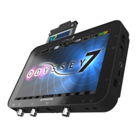
There are seven connector ports on the bottom side of the Odyssey7 (left to right)
PWR on Power input socket to Odyssey7 (see Geng started – power). Just in front of the pwr On port is a
buon, which is a Force power On/O control. Hold buon ve seconds to force power o. This is
only to be used if standard power on or o procedures fail (see Geng started – inializing).
SDI in BNC connector for 3G-SDI input
LTC io BNC connector for linear Timecode input/output
HDMI in HDMI 1.4 input from HDMI video source.
HDMI Out HDMI 1.4 output to external monitor or other device
SDI Out BNC connector for 3G-SDI output
AUDIO in 3.5mm mini-phone stereo socket for analog audio in.
This input will be enabled in a free future rmware update.
AUDIO Out 3.5mm mini-phone stereo headphone socket.
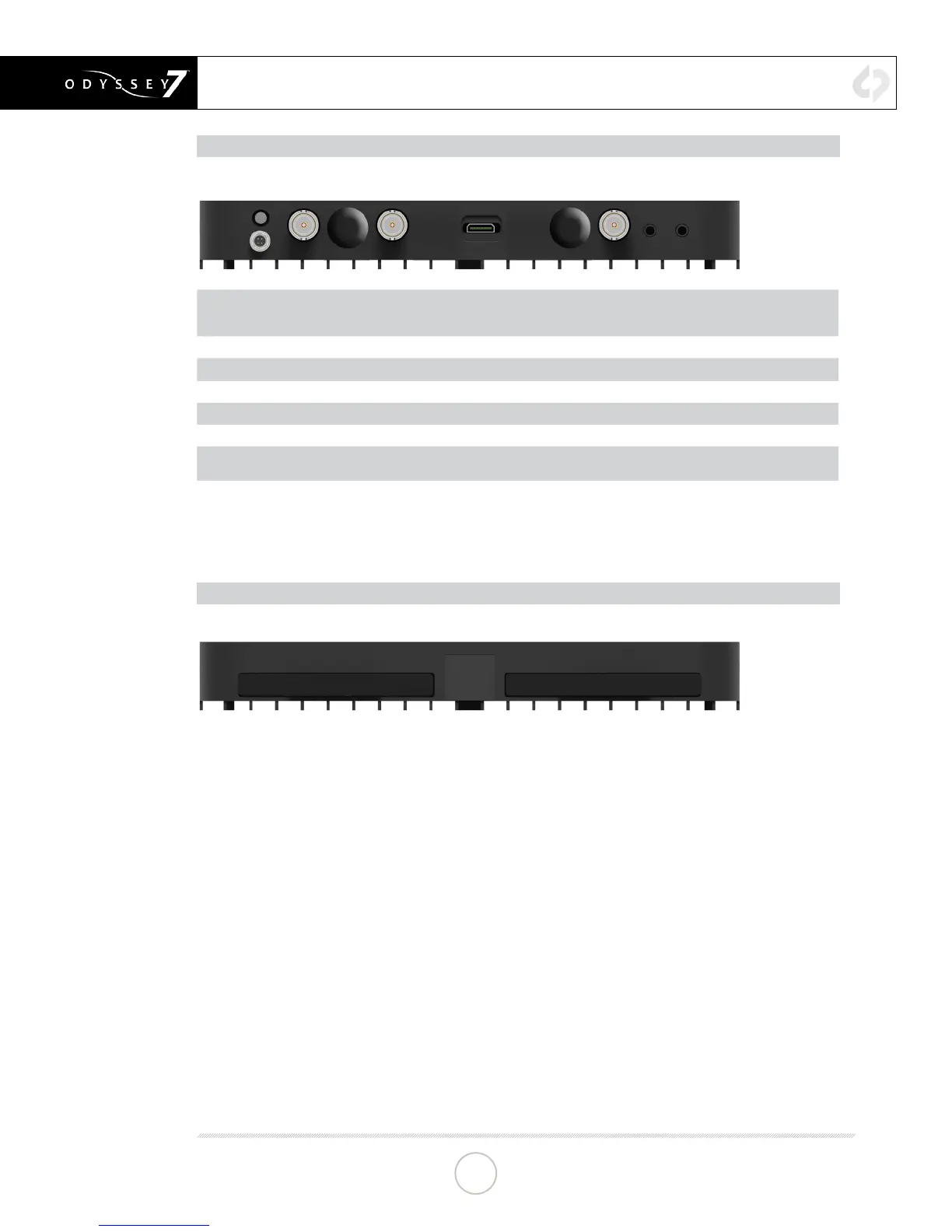
ODYSSEY7 - TOP
There is a single Solid State Drive (SSD) slot on the top of the Odyssey7
Only Convergent Design 256GB, 512GB and 1TB Odyssey SSDs can be used to capture video on the
Odyssey7. The Odyssey Utility Drive can be used for rmware updates and other future functions, but
not to record video les.
To mount SSD, insert connector-end rst with the label facing forward and the handle near ush with the
back of the Odyssey7. Push gently but rmly until the handle ange is ush with the top of the Odyssey7.
It is a snug t, but the SSD should insert smoothly.
ANATOMY
9