4-10
CHAPTER 4 REPAIR PROCEDURES
5. Refer to Section 4.5.1 and check overload stops on the new assembly.
6. Lift the Load Cell Assembly out of the Bottom Housing and replace with the new one. Install screws.
7. Refer to Figure 3-2 and the label on the replacement Load Cell.
8. Solder the Load Cell wiring to the Main PC Board. Make sure that the color coded wiring is installed
in the correct locations.
9. Reconnect the battery and power connectors to the Main PC Board and connect the battery terminal
wiring to the battery.
10.Connect the Display Cable from the Display PC Board to the Main PC Board.
11.Install the Main PC Board into position in the slots on the Bottom Housing and secure with the
screws and washers previously removed.
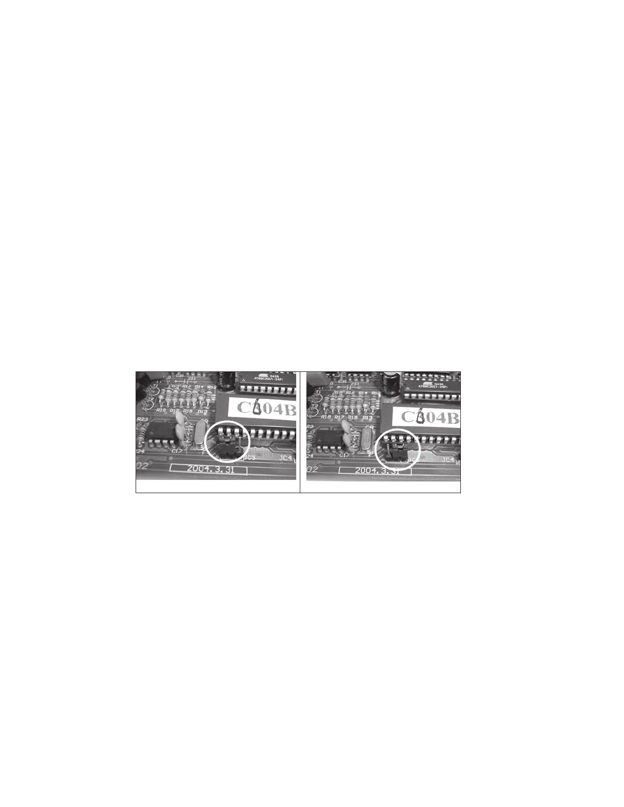
12. Refer to Figure 4-15 and move the Main PC Board Jumper from normal to service position.
4.4 REPLACING THE LOAD CELL ASSEMBLY (WITH FRAME) (Cont.)
Figure 4-15. Main PC Board Jumper Positions.
NORMAL
SERVICE
13.Position the Top Housing in place over the scale temporarily and install the Platform Support and
Platform in place.
14. Calibrate the scale according to the Instructions in Appendix A. After calibration, replace the
jumper into the normal position.
15.Reassemble the scale and replace the Platform Support and Platform on top of the scale.
16.Turn the scale off then on. It will go through all the self-testing. When self-testing is completed,
the scale should work nomally.
17.After repair, perform Performance Tests, see Section 3.6.
 Loading...