24 Model 5380 PFPD Operator’s Manual
Rev. 3.1
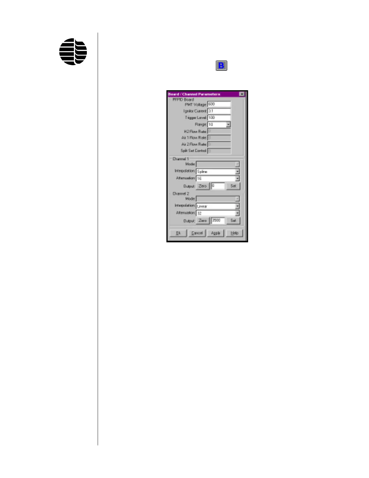
Board/Channel Parameters Screen
To access the Board/Channel Parameters screen, go to the Parameters menu and
click on Board/Channel or click on the
button located on the toolbar. See
Figure 3.3.
The Board Parameters screen is used to set the parameters for the PFPD Board
and the Channel 1 and Channel 2 output signals. The PFPD Board parameters
control the operation of the PFPD, the pneumatics, and the output signal. The
Channel 1 and Channel 2 boxes allow specification of the output signals that are
to be sent to the data integration device, and they set parameters used to digitize the
PMT signal before it is sent to the output handling device. Two channels are
provided because the Detector Controller can simultaneously process and send two
signals. The function of each field in this screen is as follows:
PMT Voltage Sets the voltage delivered to the photocathode of the PMT to
convert photon energy to an electrical current (0–1000 V;
default is 600 V). The PMT’s sensitivity to an analyte (repre-
sented by chemiluminescence amplitude) can be increased by
increasing the PMT voltage. (Noise usually increases as PMT
voltage is raised above some value.)
Ignitor Current Sets the current required to provide sufficient power to the
ignitor for reliable flame initiation (0.0–3.30 A; 2.6–2.8 A is
typical).
Figure 3.3. Board/Channel
Parameters Screen
 Loading...