56 Model 5380 PFPD Operator’s Manual
Rev. 3.1
• Connect the oscilloscope to the PFPD either with the signal cable from the
PMT or a BNC cable from the SCOPE connector on the back panel of the
Detector Controller.
• The PFPD controller generates a trigger spike for setting the trigger on the
scope and scales the chemiluminescence output to 10 V (max.). If the
signal is off scale, check the oscilloscope input voltage setting, and verify
where the ground reference is set.
Optimizing the Combustor Flow (Sulfur)
The objective of manipulating the flow rate and mixture of combustor gases (H
2
and Air 1) is to maximize the emission lifetime of the chemiluminescence associ-
ated with the specific elements of interest. The chemiluminescence lifetime of each
element starts after a particular “delay” following the passage of the flame through
the combustor. The emissions of some elements are delayed more than others. For
example, sulfur emissions are delayed more than phosphorus and have a longer
lifetime. This description focuses on maximizing the lifetime of phosphorus and
sulfur chemiluminescence emissions.
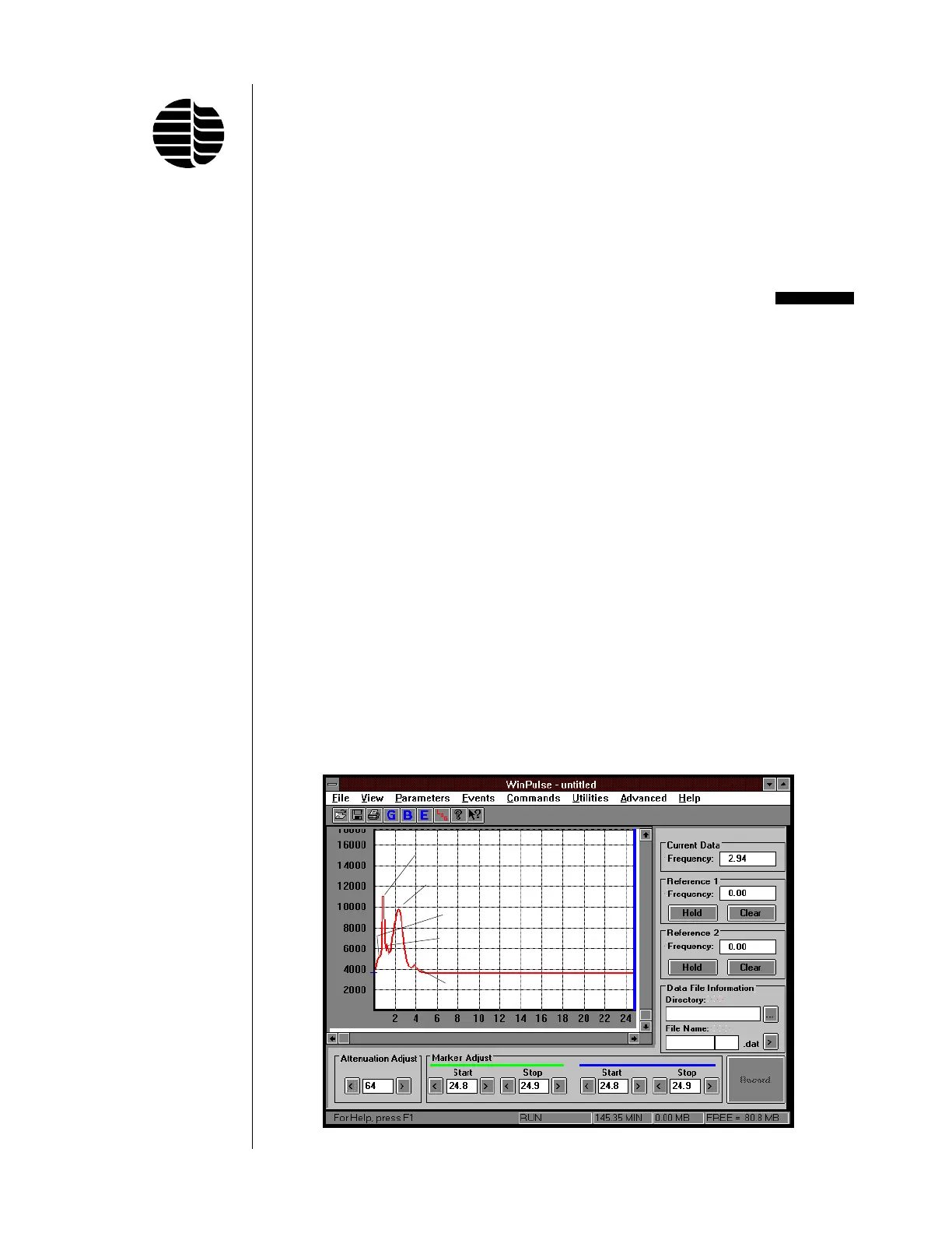
Figure 5.1 illustrates a background chemiluminescence emission when no analyte
is injected into the GC column. There are typically two major peaks, but three
other sets of smaller spikes may also be observed. The first main peak on the left of
the screen is due to chemiluminescence resulting from flame propagation through
the detector cap and hitting the top of the combustor. The second main peak
reflects the OH*, C
2
*, and CH* emissions resulting from flame propagation
through the combustor or glowing dust particles or dirt in the combustor. The
relative heights of the two main peaks are determined by the flow rates and mix-
tures of the wall and combustor gases. The flow rate of Air 2 primarily affects the
height of the first peak, and the H
2
/Air 1 mixture affects the height of the second
peak.
Figure 5.1. Primary Peaks and Secondary Spikes of PFPD Fluorescence
Peak 1 (Detector Cap)
Peak 2 (Combustor)
Spike 1 (Detector Cap)
Spike 2 (Top of Combustor)
Spike 3 (GC Column)


 To Next Page