Chapter 4 31
Installation
10. Install the appropriate analog interface boards (if required) into the GC (see
the Agilent 6890 Series Gas Chromatograph Operating Manual).
Mounting the PFPD on the GC
1. Carefully remove the PFPD assembly from its packaging.
2. Before installing the PFPD onto the GC, ensure that the following compo-
nents are attached to the detector assembly (see Figures 2.1 and 2.2):
• Check that the ignitor assembly (Part #282624) is attached to the detector
cap. If not, remove the protective cap from the ignitor connector on the
detector cap. Remove the ignitor from its protective cover taking care not
to touch the ignitor coil. Carefully insert the ignitor into the ignitor housing
and tighten the hexagonal nut (located behind the ignitor) onto the ignitor
connector.
• Check that the heater assembly (Part #252429 for Agilent 6890 GC; Part
#178954 and Part #170093 for Agilent 5890 GC) is embedded in the
detector base. If not, put the heater cable assembly down through the round
opening in the detector mounting plate (Part #280735 for Agilent 6890
GC; Part #245464 for Agilent 5890 GC). Insert the heater element (larger
diameter, metal probe) and temperature sensor (smaller diameter, white
porcelain probe) into the appropriate receptacles in the bottom of the
detector base. Do not excessively bend the wire leads protruding from the
heater element and temperature sensor at the base of the detector.
• Check that a protective plug is inserted into the column inlet fitting at the
bottom of the detector base. If not, insert a Q/qy" no-hole ferrule (Part
#197079) into the GC column nut (Part #223057) with the tapered end of
the ferrule facing into the nut. Gently screw the column nut into the bottom
of the detector base to prevent debris from penetrating the detector base
during installation.
3. Evenly pack a Q/r" thick strip of the insulation blanket (Part #280610) around
the detector base below the mounting plate so that none of the detector base
remains exposed. Do not wrap the heater cable in the packing.
!
CAUTION:
Excessive
bending of the
wire leads on the
heater or
temperature
sensor will cause
damage.
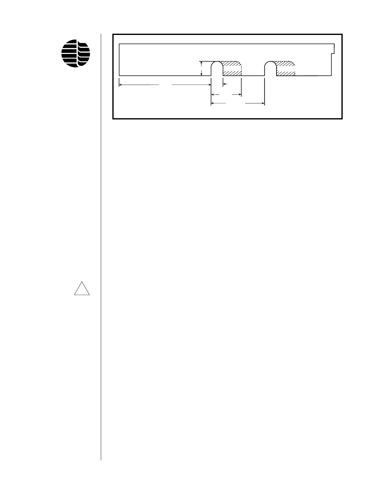
Figure 4.2. Preparing the GC Top Right Cover
Rear Detector
Position
Front Detector
Position
Remove Remove
0.853"
5.41"
0.705"
1.78"
(±0.050)
3.145"