34 Model 5380 PFPD Operator’s Manual
Rev. 3.1
5. Place the PFPD valve box mounting plate on the GC. Line up the holes in the
plate with the two pem nuts located on the GC.
6. Using two Torx screws (M4 x 10) (Part #252585), attach the valve box
mounting plate to the GC.
7. Align the PFPD mounting plate with the four threaded studs on the valve
plate. Connect the PFPD mounting plate using four #6 washers (#132589),
lock washers (#132654), and nuts (#131904).
8. Connect the cable heater/sensor extension (#296368) to the existing heater
cable. Connect the other end of the heater cable to the corresponding 4-pin
nylon sensor connector located in the electronics area above the GC
motherboard (see Figure 4.4).
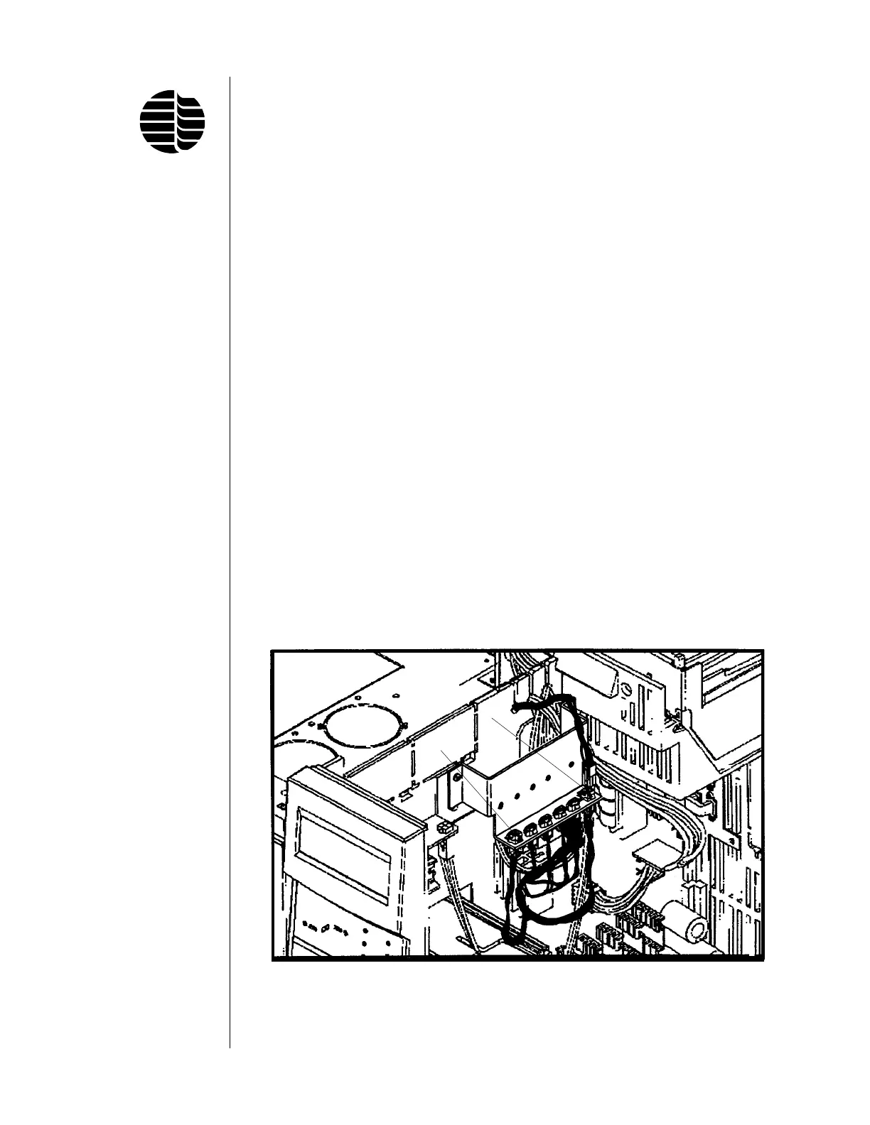
9. If both detector ports are occupied by existing detectors, the heater assembly
must be plugged in and controlled by the valve heater driver for the GC. If the
valve heater driver is installed on the GC, plug the heater cable to either the
P1 or P2 position (see Figure 4.6).
If the valve cable assembly and bracket are not already installed on the GC,
they must be ordered separately. Both the valve driver block (OI Part
#280818; Agilent G1580-00070) and the valve driver wire harness (OI Part
#280834; Agilent G1530-60660) are needed. See the Agilent 6890 GC Service
Manual for instructions on installing these items.
10. Pack the insulation around the detector base to minimize the dead space and
heat loss.
Figure 4.6. Valve Heater Driver
P1
P2
 Loading...