7.
Connection Diagram
43984801TH Rev.1
123 /
Oki Data CONFIDENTIAL
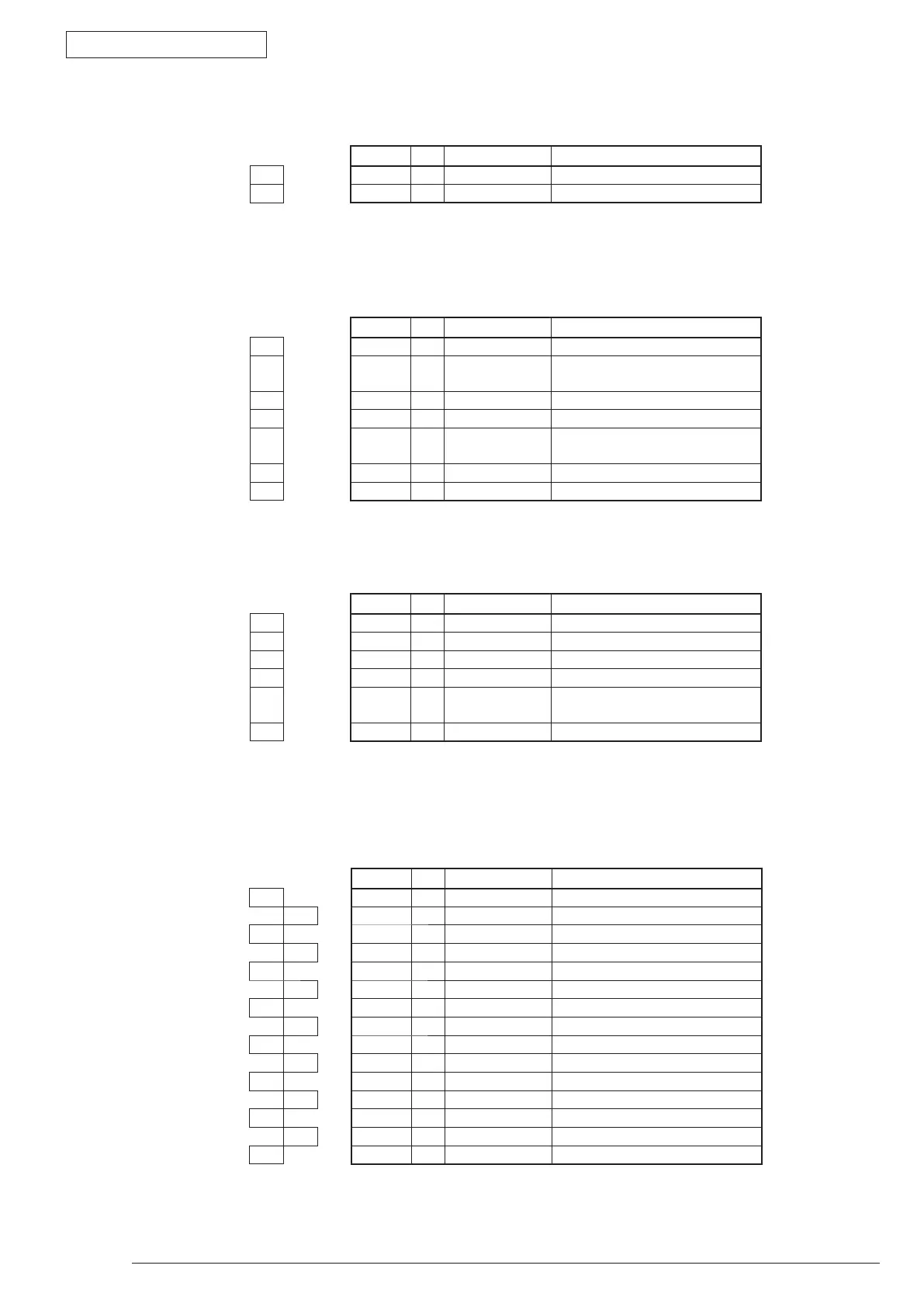
• SON Connector Pin Allocation
(Connection to the Solenoid)
Pin No. I/O Signal Function
1 1 O SON-P Solenoid Drive Power
2 2 C SGND Analog Ground
• PE1STD Connector Pin Allocation
(Connection to the front sensor)
Pin No. I/O Signal Function
1 1 O 5V Logic Circuit Power Supply
2 2 C PAPER-N Detection of the media presence
in a tray
3 3 O GND Logic Ground
4 4 C 5V Logic Circuit Power Supply
5 5 O 1ST_DUP-N 1st Tray/ Detection of the Duplex
unit
6 6 C GND Logic Ground
7 7 NC NC Not connected
• EXRCO Connector Pin Allocation
(Connection to the Rear Sensor)
Pin No. I/O Signal Function
1 1 O 5V Logic Circuit Power Supply
2 2 C EXIT-N Detection of the media output
3 3 O GND Logic Ground
4 4 C 5V Logic Circuit Power Supply
5 5 O RCOPN-N Detection whether to open or
close the rear cover
6 6 C GND Logic Ground
• LCDPNL Connector Pin Allocation
(Connection to the Operator Panel)
Pin No. I/O Signal Function
1 1 C GNDLCD Logic Ground
2 2 O LCD_RS Register Selection
3 3 O LED1 LED ON
4 4 O 5VLCD Logic Circuit Power Supply
5 5 O LED2 LED ON
6 6 O LCD_CSB Register Clear
7 7 I SW6 Switch 6
8 8 O LCD_CLK Serial Clock
9 9 O LCD_D
0
Serial Data
10 10 O LCD_RST LCD Reset
11 11 I SW1 Switch 1
12 12 I SW4 Switch 4
13 13 I SW2 Switch 2
14 14 I SW5 Switch 5
15 15 I SW3 Switch 3
For B410dn only use Pin No. 1~10, yet for B430dn use all of No. 1~15.