7.
Connection Diagram
43984801TH Rev.1
124 /
Oki Data CONFIDENTIAL
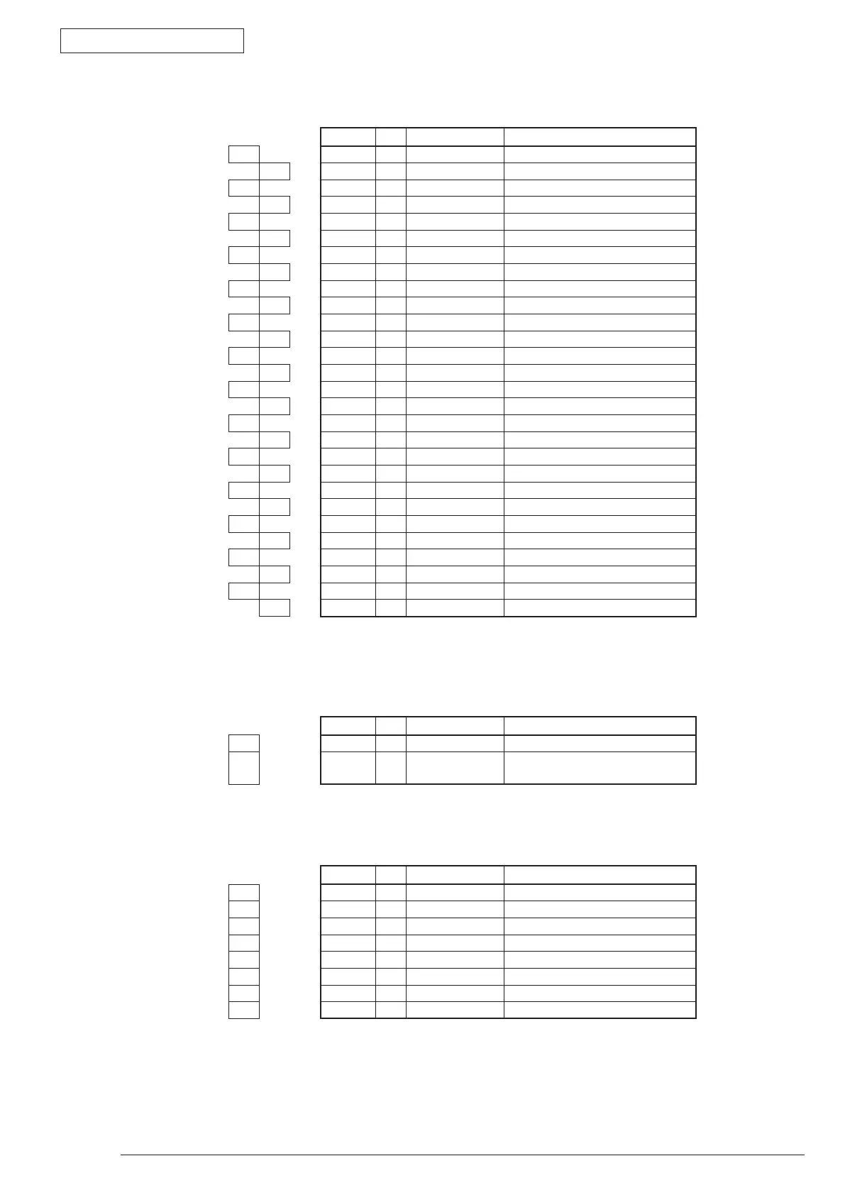
• HVIF Connector Pin Allocation
(Connection to High-Voltage power or Sensor Board I/F)
Pin No. I/O Signal Function
1 1 O CB2PWM CB2 Output
2 2 O CB1PWM CB1 Output
3 3 O CHPWM CH Output
4 4 I WRSNS Paper Detection
5 5 C GND Logic Ground
6 6 O TR2PWM TR2 Output
7 7 O TR1PWM TR1 Output
8 8 I VSEN TR1 Power Voltage Detection
9 9 I ISEN TR1 Electric Current Detection
10 10 I DB_I DB2 Electric Current Detection
11 11 I DB2_V_FB DB2 Power Voltage Detection
12 12 I SB_V_FB SB2 Power Voltage Detection
13 13 CH_I Not used
14 14 I CH_V_FB CH Power Voltage Detection
15 15 I PSIN1 Paper Detection
16 16 O DB1PWM DB1 Output
17 17 O DB2PWM DB2 Output
18 18 O SBPWN SB2 Output
19 19 O +5V +5V Power
20 20 I TONER Toner Amount Detection
21 21 C GND Logic Ground
22 22 O FANPOW FAN Drive Power
23 23 I FANALM FAN Alarm Detection
24 24 I THERM Fusing Temperature Detection
25 25 I CVOPN-N Cover-open Detection
26 26 I/O TAG EEPROM 1-wire signal
27 27 C GND Logic Ground
28 28 O FUSECUT Fuse-cut signal
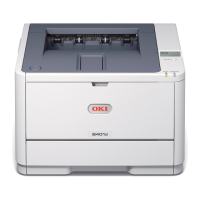
• THERM Connector Pin Allocation
(Connection to the environmental sensor)
Pin No. I/O Signal Function
1 1 O THERM1 Sensor Power
2 2 I THERM2 Environmental Temperature
Detection
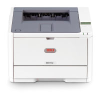
• 2NDTRAY Connector Pin Allocation
(Connection to the Option tray I/F)
Pin No. I/O Signal Function
1 1 O SCLK-N Clock
2 2 I/O DATA-N Data
3 3 I SDP-N OPT Transmission Mode
4 4 O OPCNT-N Control Signal
5 5 C 0V Logic Ground
6 6 O +5V Logic Circuit Power Supply
7 7 C 0VP Analog Ground
8 8 O +24V Motor/ Clutch Drive Power