ENGLISH
EN - 18
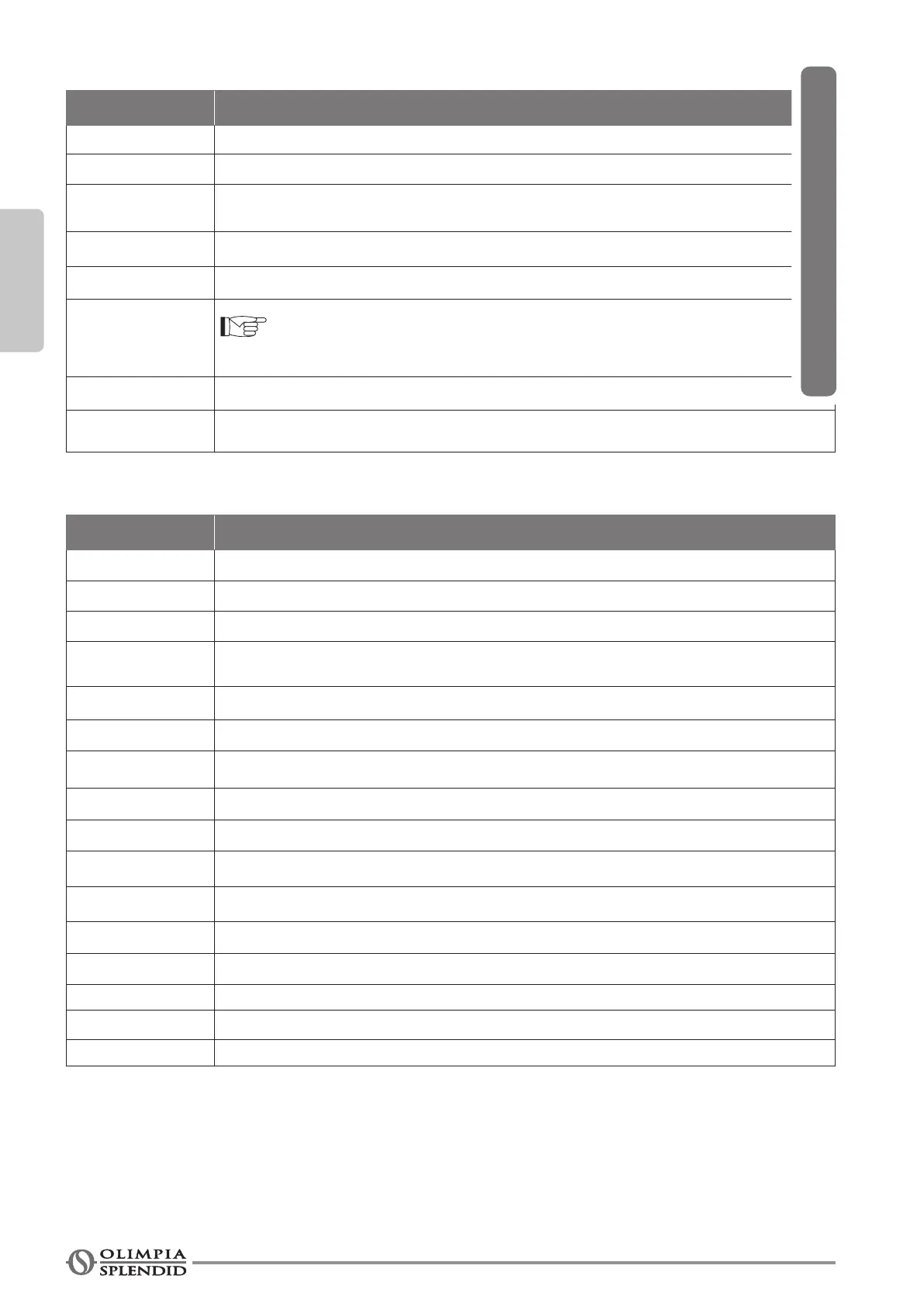
Tab_7 (diagrams “E”, “G” and “H”)
Led status Mode of operation
O Board in Stand-by (contact CV open)
On Board on (contact CV closed)
1 Blink
Temperature H2O > 20°C in summer mode or
Temperature H2O < 30°C in winter mode
2 Blinks Motor locked/disconnected or safety grille open
3 Blinks Water temperature sensor open or short circuited
4 Blinks
THIS SIGNAL IS NOT AN ALARM
At every start-up, the system checks the software version of the power board
5 Blinks The motor feedback indicates a speed > 1400 rpm
6 Blinks
The motor feedback indicates a speed < 100 rpm
(see locked fan function)
Tab_8 (diagrams “E”, “G” and “H”)
Terminal box Connections
H2O 2 water temperatures sensor (optional)*
M1
DC motor
M2
Flap motor
S1
Intake grille safety microswitch
(to be connected only on some models, removing the bridge)
F - N
Board supply
230V - 50Hz
Y1
Solenoid valve 230V - 50Hz, 1A
CFG Jumper open to select the mode ‘contacts’
COM Common
EV Solenoid valve management / Fan enabling **
MAX Max speed
MED Medium speed
MIN Minimum speed
SIL Super-minimum speed
E / I Summer/Winter mode selection (Open: Winter)
Led
Mode/status indication
SW1
Machine conguration selector
* the water sensor is optional: if connected, the board will allow operation of the fan only with water temperature suitable
for the selected mode of operation (higher than 30°C in winter mode and lower than 20°C in summer mode). If it is not
connected, the board shall not carry out any check of water temperature.
** The fan operation is enabled only when the EV input is closed. Follow the connection diagram to the EV input even if
the valve management is not required. When the EV input is closed, only output Y1 is energised.
WITH FLAP