2-2-1
2-2 Electrical Parts Layout
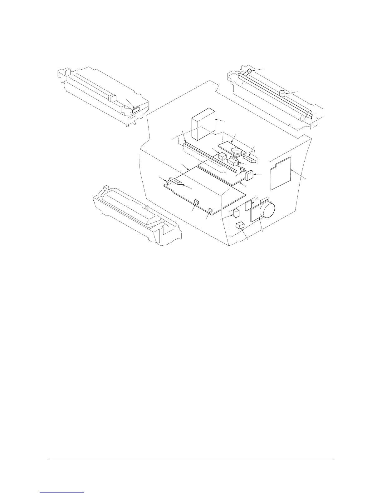
2-2-1 Electrical parts layout
(1) Electrical parts layout
Figure 2-2-1 Main frame
1. Engine/high voltage PWB ............................ Controls the input/output of electrical parts and generates the high volt-
age.
2. Power source PWB...................................... After full-wave rectification of AC power source input, switching for con-
verting to 24 V DC and 5 V DC for output.
3. Connect PWB .............................................. Consists the buzzer and wiring relay circuit.
4. Eraser lamp PWB ........................................ Eliminates the residual electrostatic charge on the drum.
5. Zener PWB .................................................. Adjusts the main charger grid electrostatic potential.
6. Registration sensor ...................................... Detects the timing of primary feeding and paper jam.
7. Paper sensor................................................ Detects paper in the paper cassette.
8. Exit sensor ................................................... Detects paper jam in the fuser unit and paper exit section.
9. Toner empty sensor ..................................... Measures toner in the toner container.
10. Waste toner full sensor ................................ Detects the waste toner reservoir (drum unit) being full.
11. Interlock switch ............................................ Monitors whether the top cover is open and cuts off the 24 V DC power-
source.
12. Power switch................................................ Turns ON/OFF the AC power source.
13. Fuser thermistor........................................... Measures the heat roller temperature.
14. Main motor ................................................... Drives the entire machine.
15. Cooling fan motor......................................... Cools the interior of machine.
16. Power source fan motor............................... Cools the power source PWB.
17. Polygon motor.............................................. Drives the polygon mirror.
18. Feed clutch .................................................. Controls the paper cassette paper feed.
19. Registration clutch ....................................... Controls the primary paper feed.
20. AC inlet ........................................................ Connects the AC power source.
21. Thermal cutout ............................................. Shuts off the power source to the heater lamp when the heat roller
reaches extremely high temperature.
22. Heater lamp ................................................. Energizes the heat roller.
23. Fax control PWB .......................................... Modulates, demodulates, compresses, decompresses and smoothes out
image data, and converts resolution of image data. Also, controls con-
nection to the telephone line.
Laser
scanner unit
Developer unit
Drum unit
Fuser unit
(d-Copia164MF only)
Y107330-8 Service Manual
 Loading...