L
lliuJul 31, 2025
What to do if my Olivetti Printer displays a misfeed?
- SSteven AlexanderJul 31, 2025
If your Olivetti Printer displays a misfeed error, open the indicated door, remove the jammed paper, and then close the door securely.
What to do if my Olivetti Printer displays a misfeed?
If your Olivetti Printer displays a misfeed error, open the indicated door, remove the jammed paper, and then close the door securely.
Lists items like paint-locked screws, red-painted screws, variable resistors, and PWB removal precautions.
Provides lists of parts for disassembly, assembly, and cleaning, with reference pages.
Details the steps for disassembling and assembling various components of the manual bypass tray.
Step-by-step guide for removing the manual bypass tray feed roller.
Step-by-step guide for removing the manual bypass tray separation roller.
Instructions for removing the left, right, and upper covers of the manual bypass tray.
Detailed procedure for removing the entire manual bypass tray unit.
Instructions for cleaning the manual bypass tray feed and separation rollers.
Guide on cleaning the manual bypass tray feed roller using a damp pad.
Guide on cleaning the manual bypass tray separation roller using a damp pad.
Steps to access and perform state confirmation within the service mode.
Displays the sensor check screen interface and its elements.
Details sensor symbols, panel display, part names, and operation characteristics.
Adjustments related to the printer's image area and alignment.
Procedure for adjusting the leading edge alignment of prints.
Procedure for adjusting the horizontal centering of prints.
Procedure for adjusting the centering of prints on the backside of duplex copies.
Adjusts the width settings for the manual bypass tray for accurate paper feeding.
Adjustments related to the mechanical components of the bypass unit.
Procedure for adjusting the bypass paper size unit's mechanical alignment.
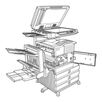
Explains how misfeeds are displayed on the main body's touch panel.
Steps to reset a misfeed display by clearing the jam.
Diagram showing the location of sensors related to misfeeds.
Provides solutions for misfeed errors.
Initial checks to perform when a paper misfeed occurs.
Specific troubleshooting for misfeeds in the manual bypass feed section.
Lists malfunction codes detected by the CPU and displayed on the touch panel.
Provides solutions for detected trouble codes.
Solution steps for the C0211 error code related to manual feed operation.