Do you have a question about the Olivetti PR2 E and is the answer not in the manual?
Overview of manual structure, contents, bibliography, and key printer information.
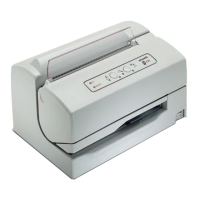
Overview of the PR2 E printer, its capabilities, target environments, and key differences from PR2.
Details the various factory configurations of the PR2 E printer.
Lists key specifications like printing module, speed, quality, cartridge, feed, size, console, emulations, dimensions, power.
Describes the function of the magnetic device and MICR reader for check processing.
Lists variable configurations for voltage, frequency, power cords, and CRT firmware.
Details specifications for handling ordinary forms and savings books, including dimensions and types.
Describes available accessories for the PR2 E printer, focusing on ribbon cartridges.
Illustrates and labels the external and internal major components of the PR2 E printer.
Presents a block diagram of the basic PR2 E machine, showing interconnections.
Explains firmware, supported emulations, character sets, print modes, and speeds.
Identifies the primary operating controls of the printer: power switch, console buttons, and lifting lever.
Describes the power switch and details the console layout with LEDs and buttons.
Explains the functions of the console buttons and how they change based on machine state.
Defines LED meanings, error classification, and fault identification via LEDs.
Details button and LED functions for IBM 9068/4722, SNI 4915/4904, and IBM Proprinter emulations.
Explains the function and use of the lever for accessing the paper path.
Provides precautions for electrical supply, environmental conditions, and printer placement.
Guides through unpacking, checking contents, removing retainers, and installing the ribbon cartridge.
Instructions for installing the printer, verifying voltage, and performing an off-line print test.
Details the information provided by the printer's self-test and shows examples of test output.
Instructions for connecting RS232C, Serial+USB, and Parallel interface cards.
Describes the Serial+USB card, its connectors, and pin-out.
Details the Parallel Interface Card, its connectors, and pin-out.
Outlines final testing procedures and essential information for operator training.
Guides on inserting documents, savings books, and checks using automatic and manual alignment methods.
Explains document expulsion and the procedure for replacing the ribbon cartridge.
Covers causes of paper jams and detailed procedures for clearing them from different printer areas.
Describes the power-on self-diagnostic routine and how to access printer setup and support software.
Details various printer set-up parameters, including IBM and Olivetti menu options.
Explains photosensor calibration needs and shows the location of various sensors.
Details the procedure for calibrating bi-directional print alignment for different print modes.
Provides the block diagram and steps for calibrating the Top of Form position.
Explains the process for calibrating the left print margin for accurate document positioning.
Outlines the procedure for measuring document length, particularly for savings books.
Describes checks for printhead skew, signal amplitude, and magnetic read operations.
Provides an approach to servicing and analyzing faults, including operating conditions and component checks.
Categorizes printer faults and lists probable failures for easier troubleshooting.
Lists possible causes and symptoms for faults occurring during printer power-on.
Details causes for document writing failures like faded or incomplete printing.
Identifies issues related to document loading, crooked feeding, crumpling, or irregular line feeds.
Lists causes for failures in reading or writing magnetic stripes on documents.
Shows the overall interconnection diagram of the PR2 E printer's main board and peripherals.
Provides a view of the main BAPR2 board and the location of its connectors.
Details the pin assignments for various connectors on the PR2 E main board.
Describes the magnetic options card (PR2MAGN) for managing the horizontal magnetic device.
Shows a view of the PR2MAGN card and lists its connector pin assignments.
Describes the interface card providing additional serial RS232 and USB connectivity.
Details the pin assignments for the connectors on the Serial and USB Interface Card.
Describes the interface card providing a Centronics parallel interface.
Details the pin assignments for the connectors on the Parallel Interface Card.
Shows the console layout and its electrical connection diagram.
Provides information on the ALIPR2E card, its connectors, and fuse.
Outlines recommended cleaning for the printer's case, paper paths, and magnetic read head.
Describes manual head cleaning and maintenance of the paper edge detection brush.
Lists lubrication points for the basic machine, including grease and oil types.
Details specific lubrication points for the horizontal magnetic device/MICR assembly.
Introduces the structure for describing mechanical adjustments: condition, objective, procedure, and notes.
Details adjustments for the document feed belt tension and print bar distance.
Explains parallelism adjustment for the print bar and the tab mechanism adjustment.
Covers checking front tab positioning and adjusting roller gears for proper mesh.
Details adjustments for the front pressure roller and the tab opening mechanism.
Guides on adjusting the carriage feed belt tension and the magnetic device door coplanarity.
Explains positioning the press and mounting the assembly onto the magnetic device/MICR.
Provides crucial safety and procedural guidelines for all disassembly and reassembly operations.
Details the steps for removing the printer's outer case and console.
Guides on removing the mechanical assembly and the printhead flat cable.
Provides steps for removing and reinstalling the printhead and its photosensor.
Details removing the upper mechanical assembly and the paper feed motor.
Guides on removing the printhead movement motor and carriage reset photosensor.
Details removing roller tray, services motor, and feeder photosensors.
Guides on removing the print bar, main board, and power supply assembly.
Introduces disassembly of basic machine options, specifically the magnetic device/MICR.
Details the process for removing and reinstalling the magnetic device/MICR motor.
Guides on removing and reinstalling the magnetic device/MICR head assembly.