Y100250-48-8
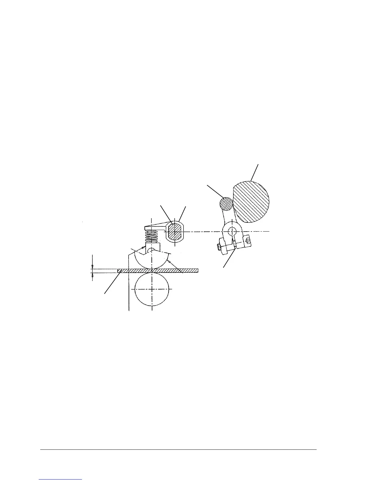
8.7 FRONT PRESSURE ROLLER ADJUSTMENT
MACHINE CONDITION:
Service cam with its minimum throw area facing the probe roller.
OBJECTIVE ADJUSTMENT:
Make sure that there is a small clearance between the probe roller (7) and the service cam (6).
(To check the correctness of the adjustment remove the probe and, without changing the fase, check
for a slight clearance between the roller and cam without loading the springs. There must be no
clearance when the probe is inserted again).
PROCEDURE:
Insert an 0.5 mm thick probe (1) between the pressure rollers (5) and the feed rollers (8); by acting on
shaft (2), position the three levers (3) so that they come into contact with the springs and then tighten
screws (4) with a torque of 20 Kgcm while holding the roller against the cam's smallest radius.
Fig. 8-7
Note: The adjustment value can vary for certain non-standard products.
6
7
3
2
4
5
1
0,5