Service ManualY100250-4 8-9
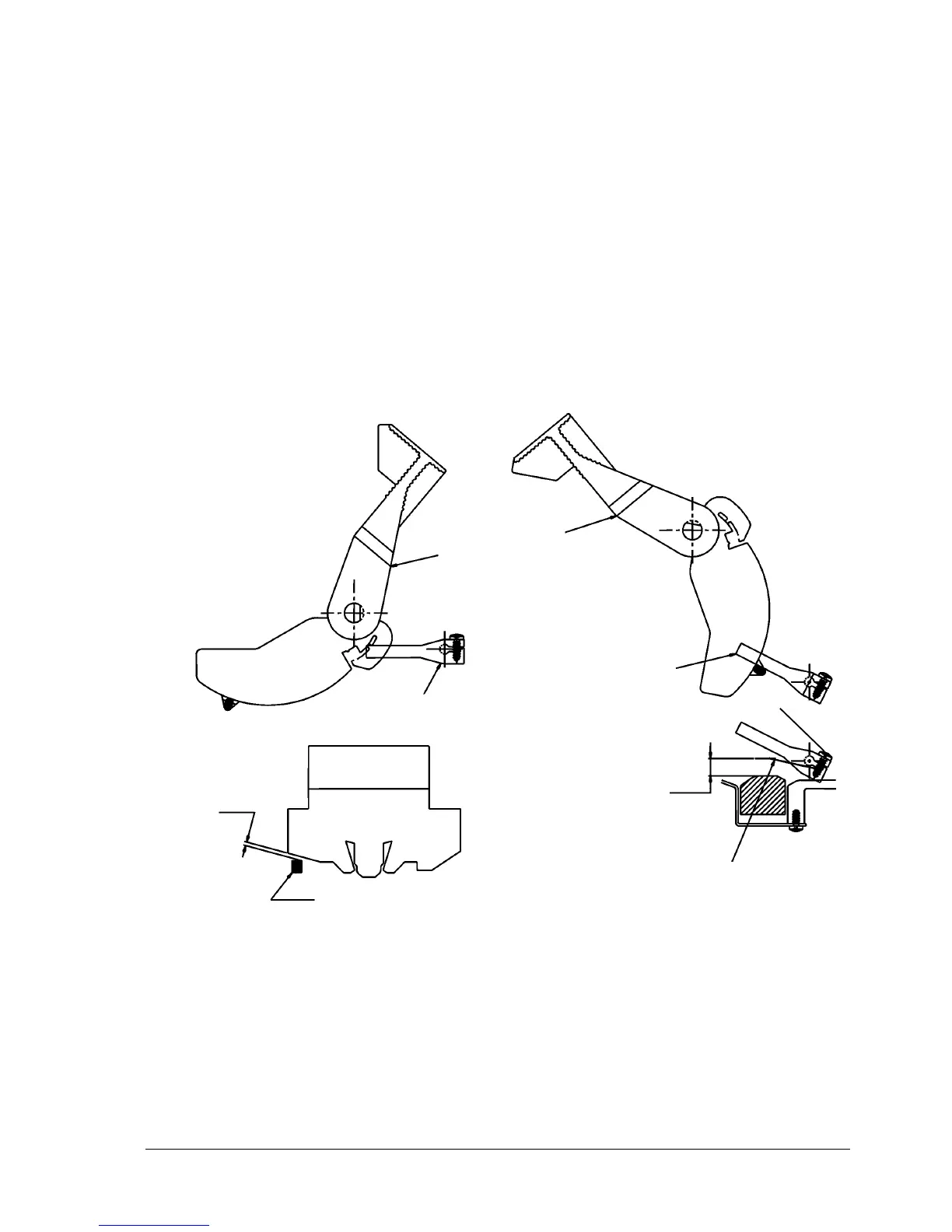
8.8 TAB OPENING ADJUSTMENT
MACHINE CONDITION:
With the upper mechanical assembly in its working position and with the printhead carriage against the
left side, position and secure lever (1) on the shaft with a clearance of 1.5 mm between the knob and
balancer (with respect to the profile of the carriage).
Upper mechanical assembly lifted and lever (1) against the lifting lever control pin (2).
OBJECTIVE ADJUSTMENT:
A distance of between 5 and 8 mm between the edge of the tab (3) and the center of the print bar.
PROCEDURE:
Turn screw (4) that secures lever (1) on the tab shaft.
Note: This adjustment must be performed after the platen and tab adjustments.
Fig. 8-8
1
2
2
1
1
1,5
5-8
3
4
PRINTHEAD
CARRIAGE