Do you have a question about the Olivetti PR2 and is the answer not in the manual?
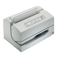
Details the PR2 as a specialized mid-range printer for banking environments, highlighting its versatility and options.
Provides a comprehensive overview of the PR2 printer's technical specifications, including print module, speed, and dimensions.
Details the technical specifications of the PR2 scanner, including sensor type, resolution, and scanning speed.
Explains the MICR device's function in reading magnetic ink characters on checks using CMC7 and E13B standards.
Lists product variables such as voltage, frequency, power cord types, user's guides, document alignment, and cover options.
Details the specifications for single and multicopy documents, including dimensions, weights, and copy capabilities.
Outlines the parameters for bank books, including thickness, page differences, cover thickness, and binding types.
Describes the available ribbon cartridges for the printer, including nylon snug cart black and indelible nylon snug cart.
Illustrates and labels the external controls and features of the PR2 printer.
Diagrams and identifies the key internal components of the PR2 printer, including boards, motors, and print head.
Presents block diagrams showing the basic machine with magnetic options and the scanner machine with magnetic options.
Details the printer's firmware, including supported emulations and optional emulations like IBM 4722 and SNI 4904.
Lists print modes with their characteristics (cpi) and specifies reference standards for optical characters (OCR A, OCR B).
Describes the location and function of the printer's bipolar power switch.
Explains the PR2 printer console, detailing its LEDs, keys, and circuit breaker for cover detection.
Details the functions of the LOCAL, STATION 1/EJECT, and STATION 2/NLQ keys and their behavior in different modes.
Explains the status indicated by the ON, READY, LOCAL, STATION 1, and STATION 2 LEDs on the printer console.
Classifies printer faults into fatal errors and recoverable errors, detailing how LEDs indicate these faults.
Describes the console layout, key functions (BREAK, STATION 1, STATION 2), and LED meanings specific to IBM 4722 emulation.
Details the console layout, key functions (STOP, EJECT), and LED meanings for the SNI 4904 emulation.
Explains the location and use of the lifting lever for accessing the paper path to clear jams.
Provides essential precautions for printer installation, focusing on power supply, environment conditions, and physical placement.
Specifies requirements for the power socket, grounding, and avoiding connection with equipment causing electrical disturbances.
Details optimal environmental conditions (temperature, humidity) and warnings about dust, dirt, and static electricity.
Provides guidance on safely installing and positioning the printer, ensuring proper ventilation and access for paper removal.
Lists the items included in the printer packaging and instructions for checking the contents upon arrival.
Step-by-step instructions for preparing the printer after unpacking, including removing securing devices and installing consumables.
Guides through positioning the machine, connecting power, and initial power-on checks, referencing error messages if needed.
Explains how to perform an off-line print test to verify printer functionality before system connection.
Provides the procedure to initiate the print test, involving powering off, powering on with a key pressed, and inserting paper.
Describes the information obtained from the print test, including firmware release, emulation, and parameters.
Details the procedures for connecting the printer via RS232C serial and IEEE 1284 parallel interfaces, including parameter settings.
Outlines the Print Test and RUN-IN Test procedures for verifying maintenance interventions and overall machine efficiency.
Provides essential information for the operator on using the console, inserting documents, replacing cartridges, and clearing jams.
Explains document insertion with automatic alignment, passbook folding, and the importance of document condition.
Details manual alignment procedures for savings books, especially with magnetic strip options, and proper positioning.
Covers inserting documents for MICR and scanner read operations, using reference strips for proper alignment.
Provides step-by-step instructions for replacing the ribbon cartridge, both with the machine powered off and powered on.
Details common causes of paper jams and procedures for clearing jams from the front insertion slot, inside the printer, and at the rear output.
Explains the printer's autodiagnostics cycle at power-on and how LED status indicates potential failures.
Describes how to obtain a printout of the machine's setup and configuration parameters using the print test.
Outlines the procedure for accessing the setup environment, emphasizing that it is for service engineers only.
Details how to activate the setup environment and explains the function of each key within this mode.
Lists and explains configuration parameters found in the setup menu, including emulation, draft speed, LQ type, and interface settings.
Details specific interface parameters for the RS232 connection, such as Baud Rate, Bit/Char, Parity, and Stop Bit.
Explains parameters for parallel and dual interfaces, including Strobe Active and Paper Edge Detection.
Provides flow charts illustrating the navigation and options within the Olivetti and IBM emulation setup menus.
Presents a flow chart for navigating the setup options specific to the SNI 4904 emulation.
Details the parameters specific to the IBM menu, including Passbook, Binding, Char Set, PC Set, and character tables.
Lists parameters for the Olivetti PR2 menu, covering Passbook, Binding, Char Generator, and character sets.
Specifies parameters for the Olivetti PR40+ emulation, including Passbook, Binding, and Line Buffer settings.
Details parameters for the Olivetti PR2845 emulation, covering Passbook, Binding, Side, and character definitions.
Outlines the procedure for activating the setup environment for IBM 4722 emulation.
Lists configuration parameters for the IBM 4722 emulation, including Draft Speed, LQ Type, and Interface settings.
Details IBM 4722 menu parameters like Passbook, Binding, Char Set, PC Table, and character definitions.
Describes the process to activate the setup environment for SNI 4904 emulation.
Provides instructions for adjusting the printer's photosensors, including paper presence, front alignment, autoborder, and rear alignment.
Detailed steps for adjusting photosensors using a special mylar code and checking for successful calibration via LED patterns.
Explains how to adjust bidirectional printing alignment for various print modes to ensure correct row alignment.
Guides on adjusting the distance between the form's Top of Form (TOF) and the first print line.
Details the procedure for setting the distance between the document's left edge and the first print character.
Explains how to measure document length for passbook magnetic stripe management, enabling faster processing.
Covers adjustment of skew and signal amplitude for the horizontal magnetic unit option using an oscilloscope.
Details the adjustment procedure for the MICR check reader, focusing on E13B format and signal amplitude.
Explains the adjustment of skew and signal amplitude for the vertical magnetic unit option using an oscilloscope.
Describes the procedure for calibrating the scanner and left margin, including steps for success and failure.
Provides instructions for adjusting the scanner brush distance to ensure proper scanner operation.
Introduces a technical approach to servicing for less experienced technicians, covering fault information and operating conditions.
Emphasizes collecting information from the operator and printer regarding fault occurrence, repetition, and conditions.
Guides on analyzing the working environment, accessories, modules, and printer operating condition for fault diagnosis.
Explains how to examine obtained information to recognize and pinpoint the specific fault on the machine.
Advises on using experience and information to logically find the root cause of a fault, starting from the most probable.
Details making repairs to restore machine functions and refers to relevant chapters for detailed information.
Recommends running a complete test after job completion to verify fault resolution and check for new issues.
Categorizes printer faults into power-on, document write, document handling, magnetic stripe, and scanning faults for easier search.
Lists common power-on faults and their potential causes, such as line voltage issues, damaged cords, or board failures.
Identifies potential causes for document write failures like faded, incomplete, or unaligned printing.
Details causes for document handling issues such as documents not loading, moving crookedly, or having irregular line feeds.
Lists possible causes for failures in magnetic stripe read/write operations, including setup, dirty heads, or faulty boards.
Covers faults related to document scanning, such as poor image quality, lateral faults, or deformed images.
Provides a high-level overview of the printer's internal wiring and connections between main boards and options.
Illustrates the BAPR2 main board and identifies the location of its various connectors.
Shows the layout of the BAPR2 main board for the basic printer version with RS 232C interface.
Depicts the layout of the BAPR2 main board for the basic printer version with RS 232C and Centronics interfaces.
Details the pin assignments and signals for connectors on the BAPR2 main board, including parallel, RS232, and console interfaces.
Presents the cabling diagram for the PR2 scanner, showing connections to main boards and options.
Illustrates the PR2 scanner main board and identifies the location of its connectors.
Shows the layout of the PR2 scanner main board with its various components and connectors.
Details the pin assignments and signals for connectors on the PR2 scanner main board.
Describes the ALIPR2 board, its voltage codes, and fuse values.
Lists connector signals and fuse values for the ALIPR2 board, related to line voltage input and transformer connections.
Introduces cards for magnetic and MICR options, including PR2MAGN and PR2MIMAG boards.
Illustrates the PR2MAGN board layout and identifies the location of its connectors.
Details the connector signals for the PR2MAGN board, including main board, magnetic motor, and magnetic head connections.
Shows the layout and connector locations for the PR2MIMAG board, used for magnetic and MICR functions.
Details the connector signals for the PR2MIMAG board, covering MICR adjustment, magnetic head, and transport motor.
Illustrates the layout and connector locations for the PR2VER board.
Details the connector signals for the PR2VER board, including connections to the main board and magnetic unit components.
Shows the console layout and its electrical diagram, detailing LED and switch connections.
Provides advice on periodically cleaning internal parts for optimal printer function, including case and paper paths.
Instructions for cleaning the printer's external case using a damp cloth, avoiding corrosive substances.
Details cleaning all document paths, including rollers and feeders, to remove paper or ribbon residues.
Describes the dry cleaning method for the reset printhead photosensor reflective sensor.
Instructions for cleaning the scanner's protective glass using a soft damp cloth.
Explains the use of a special card for cleaning horizontal magnetic devices or the MICR unit.
Differentiates between automated cleaning procedures initiated by the system and manual cleaning performed by a technician.
Discusses the brush for cleaning the paper edge detection photosensor and its replacement criteria.
Provides a table detailing lubrication points for the basic printer machine, including codes for grease and oil.
Lists lubrication points for the horizontal magnetic device, including carriage slide shafts and door mechanisms.
Details lubrication points for the vertical magnetic device, such as guide shaft, carriage pin, and motor cam.
Lists lubrication points for the scanner, including scanner cam gear and continuous pinion gear.
Covers mechanical adjustments for the basic PR2 printer without any additional options installed.
Details the procedure for adjusting the tension of the document feed belt using a specific sag measurement.
Explains how to adjust the distance between the print head needles and the probe roller.
Details the procedure for adjusting the distance between the needle tips and the ribbon protection fin.
Describes the correct positioning of the paper photosensor on the print head.
Provides instructions for adjusting the print bar, ensuring a coaxial position and specific distance for the screw.
Details the procedure for adjusting the tab to ensure proper contact with the print bar and balancer.
Explains how to adjust roller gears, ensuring proper mesh and radial clearance between teeth.
Details the adjustment of front pressure rollers, ensuring small clearance between the probe roller and the services cam.
Describes how to adjust the tab opening to achieve a specific distance between the tab edge and the print bar.
Explains how to adjust the tension of the carriage movement belt.
Covers adjustments for optional components like Horizontal Magnetic/MICR devices and scanner options.
Details adjusting the carriage feed belt tension for the horizontal magnetic/MICR option.
Explains how to adjust the door of the horizontal magnetic/MICR device for planarity.
Describes the procedure for positioning the press mechanism in its working position for the magnetic/MICR device.
Details positioning the frame assembly for the horizontal magnetic device to ensure coplanarity.
Guides on checking clearance between the magnetic head and pressure roller for the vertical magnetic device.
Explains how to adjust the scanner roller clearance to ensure proper operation of the scanner assembly.
Outlines essential safety measures and precautions to be followed before starting any disassembly operation.
Provides step-by-step instructions for removing and reassembling the printer's outer case.
Details the procedure for disconnecting and removing the printer's console.
Guides on removing and reassembling the printer's main mechanical assembly.
Explains how to disconnect and remove the flat cable connecting the print head to the main board.
Details the process of removing and reassembling the printer's upper mechanical assembly.
Provides instructions for disassembling and reassembling the print head, including related components.
Guides on removing and reassembling the paper feed motor.
Details the procedure for removing and reassembling the print head movement motor.
Explains how to remove and reinstall the services motor.
Provides instructions for disassembling and reassembling the feeder photosensor assembly.
Guides on removing and reassembling the rear photosensor.
Details the procedure for removing and reinstalling the printer's main board, including firmware updates and setup.
Explains how to remove and replace the toroidal transformer, noting power requirement checks.
Guides on removing and reinstalling the power assembly, including checking power requirements for replacement boards.
Details the procedure for replacing a fuse, emphasizing the need for identical electrical characteristics.
Provides instructions for removing and reassembling the horizontal magnetic device and MICR assembly.
Guides on removing and reassembling the MICR motor.
Details the procedure for removing and reassembling the MICR head assembly.
Explains how to remove and reassemble the vertical magnetic head.
Provides instructions for removing and reassembling the scanner motor.
Guides on removing and reassembling the scanner assembly, noting spring retention.