9-10
Y100250-4
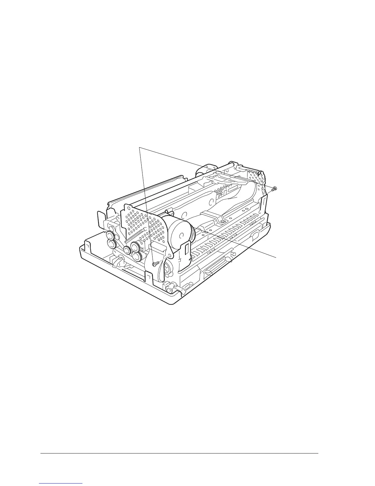
9.2.7 UPPER PART OF THE MECHANICAL ASSEMBLY DISASSEMBLY/REASSEMBLY
- Remove the printer case (section 9.2.1) and console (section 9.2.2).
- Lift the front part of the mechanical assembly off the base of the printer, partly rotating it until you are
able to reach the connectors on the main board.
- Unplug the printhead and carriage reset photosensor cables from the main board. Free the carriage
reset photosensor wires from its plastic retainers.
- Unplug connector (1) from the carriage transport motor.
- Raise the upper part of the mechanical assembly using the specific lever.
- Remove the two rear side screws (2) so as to detach the upper part of the mechanical assembly.
2
Note: During reassembly, make sure to route the cables through the appropriate slots and check the
adjustment of the roller gears (section 8.1.7).
Fig. 9-8
1