39
alarm event only if the system is armed. While the system is disarmed, an information on the
"WIRELESS SENSORS" menu screen is depicted.
If the panel finds a device having low signal power, it creates a fault in both armed and disarmed
systems.
The same happens when the battery voltage of a wireless device, drops under a critical value.
If a wireless device or an extension card does not communicate with the panel for a long time in a
disarmed system, it is recorded as an error in the events log. If the same error occurs in an armed
system, an alarm will be triggered.
If the battery level on a wireless device is low for 6 hours, a low battery fault is generated.
If the value of the RSSI (signal strength) of a wireless device is low for half an hour, then a low
signal fault occurs.
If a user gets out of technician menu and there is tamper alarm active in a wireless device, the
siren will not sound for the specific zone. However the "Tamper Alarm" event will exist on the key-
pad screen.
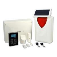
Wireless devices types
WIRELESS ZONES EXTENSION CARD - BS-479
The wireless zones extension card is responsible for connecting the wireless devices with the panel. It
has 4 LED indicators. LD3 indicates the power supply of the device. The wireless zone extension
should not be removed or installed while the panel is connected to the power supply or the battery.
There is a risk of serious damage.
WIRELESS MOTION DETECTOR - BS-470
Wireless Motion Detection features 2 DIP switches (DS1) and a Tamper Switch.
DIP Switch 1 OFF position: The device triggers alarm event as soon as the sensor gets acti-
vated.
DIP Switch 1 ON position: An alarm event is given after a time delay has elapsed since sensor
activation. That delay is set through "ZONES" menu.
DIP Switch 2 OFF position: The device is in normal sensitivity mode.
DIP Switch 2 ON position: The device is in high sensitivity mode and the detection area is now
bigger.
The wireless motion detector has also a terminal for connecting an external magnetic contact, which
when not in use must be short-circuited.
WIRELESS MAGNETIC CONTACT - BS-471
Wireless Magnetic Contact features 2 DIP switches (DS1) and a Tamper Switch.
DIP Switch 1 OFF position: Internal magnetic contact is on.
DIP Switch 1 ON position: Internal magnetic contact is off. External magnetic contact is on.
DIP Switch 2 OFF position The device triggers alarm event as soon as the sensor gets acti-
vated.
DIP Switch 2 ON position: An alarm event is given after a time delay has elapsed since sensor
activation. That delay is set through "ZONES" menu.
The position where the magnet should be placed for the internal magnetic contact to function properly
is signaled with 2 protrusions on each side of the plastic box. The magnet may be placed on one or
the other side.
At KL1 we can connect external magnetic contact which, when not in use, must be short-circuited and
the DIP Switch 1 is in the OFF position.