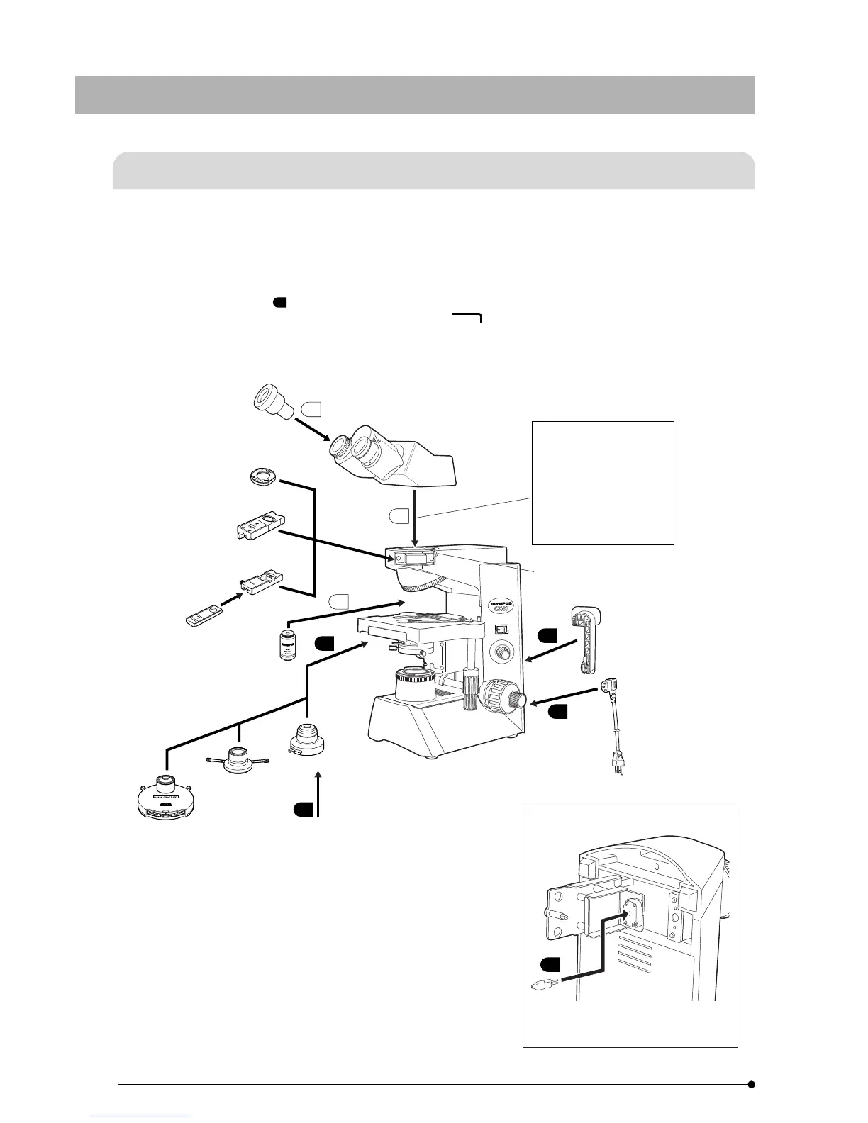
The diagram below shows the sequence of assembly of the various modules. The numbers indicate the order of assembly.
The module numbers shown in the following diagram are merely the typical examples. For the modules with which the
module numbers are not given, please consult your Olympus representative or the catalogues.
#When assembling the microscope, make sure that all parts are free of dust and dirt, and avoid scratching any parts or
touching glass surfaces.
Assembly steps enclosed in will be detailed on the subsequent pages.
}All assembly operations are possible by using the Allen wrench ( ) provided with the microscope.
21
ASSEMBLY
77
7-1 Assembly Diagram
8
7
5
4
6
2
3
1
Eyepiece
WHB10X
Analyzer
U-ANT
Gout Analyzer
U-GAN
Tarsal Plate Adapter
U-TAD
Tarsal Plate
U-TP530
U-TP137
Objective
PlanCN series
urret Condenser
CX-PCD
Darkfield Condenser
CX-DCD
Condenser CH3-CD
CH3-CDP
CX-SLC
(Slide condenser)
Filter Holder CH2-FH
Auxiliary Lens CX-AL
Simplified Phase Contrast Ring Slit
CX-PH1/PH2/PH3
Low-Power Light Adjustment Lens CX-LA
Power cord
Cord Hanger
CH3-CH
Tube clamping screw
Observation Tube
U-CBI30-2
U-CTR30-2
U-CTBI*
1
6 V, 30 W halogen bulb
Microscope Frame
CX41LF
CX41RF
Intermediate Attachment
U-EPA2
U-DO3*
4
U-APT
U-DA
U-ECA*
2
U-TRU*
2
CX-RFA-2*
2
*
3
*
1 Provided with the dedicated 10X eyepieces (field number 18).
*
2 Combination with the U-CTBI is not possible.
*
3 Also combine the eyepiece adapter (field number 18) provided with the
CX-RFA-2.(For details, refer to the instruction manual for the CX-RFA-2.)
*
4 When combination U-CTBI + U-DO3 is used by mounting the U-CBI30-2
or U-CTR30-2 on the side-view side, the field number is 18 for the main
observer and 20 for the assistant observer.