11
HARDWARE INSTALLATION
1
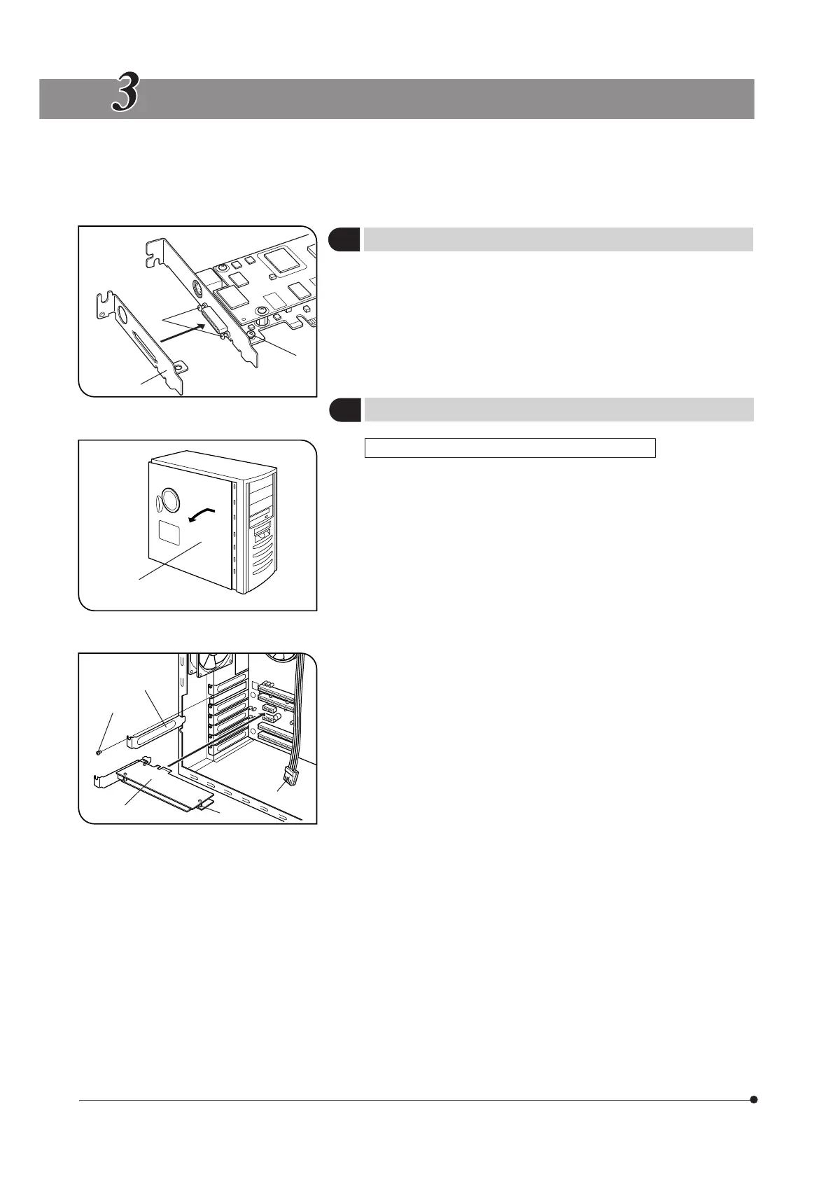
Installing the Low-Profile Bracket
(Fig. 1)
}If the PCIe extension box and the computer’s extension slot are of the
low-profile bracket specifications, it is required to replace the existing
bracket with the low-profile bracket.
1. Prepare flat-blade and Phillips screwdrivers and remove the “ – ” screws
@ and the “ + ” screw ².
2. Replace the existing bracket with the low-profile bracket ³ and attach
screws @ ².
2
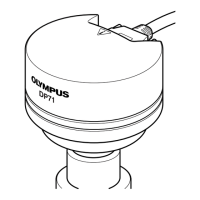
Installing the PCIe Interface Board
(Figs. 2 & 3)
DP72 (For Desktop Computer) Set (Figs. 2 & 3)
# Before installing the PCIe interface board in the computer, be sure to
read the instruction manuals for the computer in order not to damage
them.
# Be sure to turn off the computer and peripherals and unplug their
power cords before installing the PCIe interface board.
# To avoid damage due to static electricity, touch an unpainted metallic
surface of the computer with your hand to leak the static electricity
before installation.
# The SATA-to-HDD(4-pin) power conversion adapter is sensitive to
excessive force. Please handle it with care.
1. Open the cover @ of the computer.
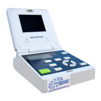
2. Remove the clamping screw ³ of the slot cover ² of an unused PCIe
slot on the motherboard and remove the cover.
3. Insert the PCIe interface board | taking care not to touch the board
surface directly by hand, and attach the slot cover using the clamping
screw removed above.
4. Connect the FDD power cable 5 from the computer’s power supply to
the power connector 6 on the PCIe interface board |.
If your computer does not have an available FDD power cable or the
FDD power cable is too short, connect the provided HDD-to-FDD power
conversion cable from the computer’s HDD power cable to the power
connector 6 on the PCIe interface board |.
And if your computer does not have an available HDD(4-pin) power cable,
connect the provided SATA-to-HDD(4-pin) power conversion adapter and
HDD(4-pin)-to-FDD power conversion cable from the computer’s SATA
power cable to the power connector 6 on the PCIe interface board |.
5. Attach the computer cover @ to the original position.
Fig. 2
@
²
³
|
5
6
Fig. 1
@
²
³
Fig. 3