15
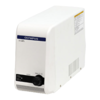
U-LGPS
This section describes the procedures to assemble U-LLG150/U-LLG150 and power cords.
5 Assembly
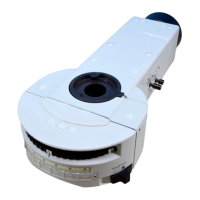
Hold the incidence side connector
A
of U-LLG150/U-LLG300 with
hand, and insert it completely to the end of the liquid light guide
insertion port of U-LGPS.
1
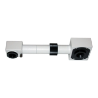
Attach U-LLGAD to the illuminator.
Tighten the clamping screw
E
of the illuminator using the Allen
screwdriver provided with the microscope.
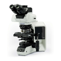
Do not turn ON the lamp while U-LGPS is not attached to
the microscope using U-LLG150/U-LLG300 and U-LLGAD.
The light from this lamp contains the UV light. Looking
directly at the light may damage your eyes. Also, it could
cause a fire.
U-LLG150/U-LLG300 and power cords are vulnerable to
bending and twisting. Be careful not to apply excessive
force.
6
7
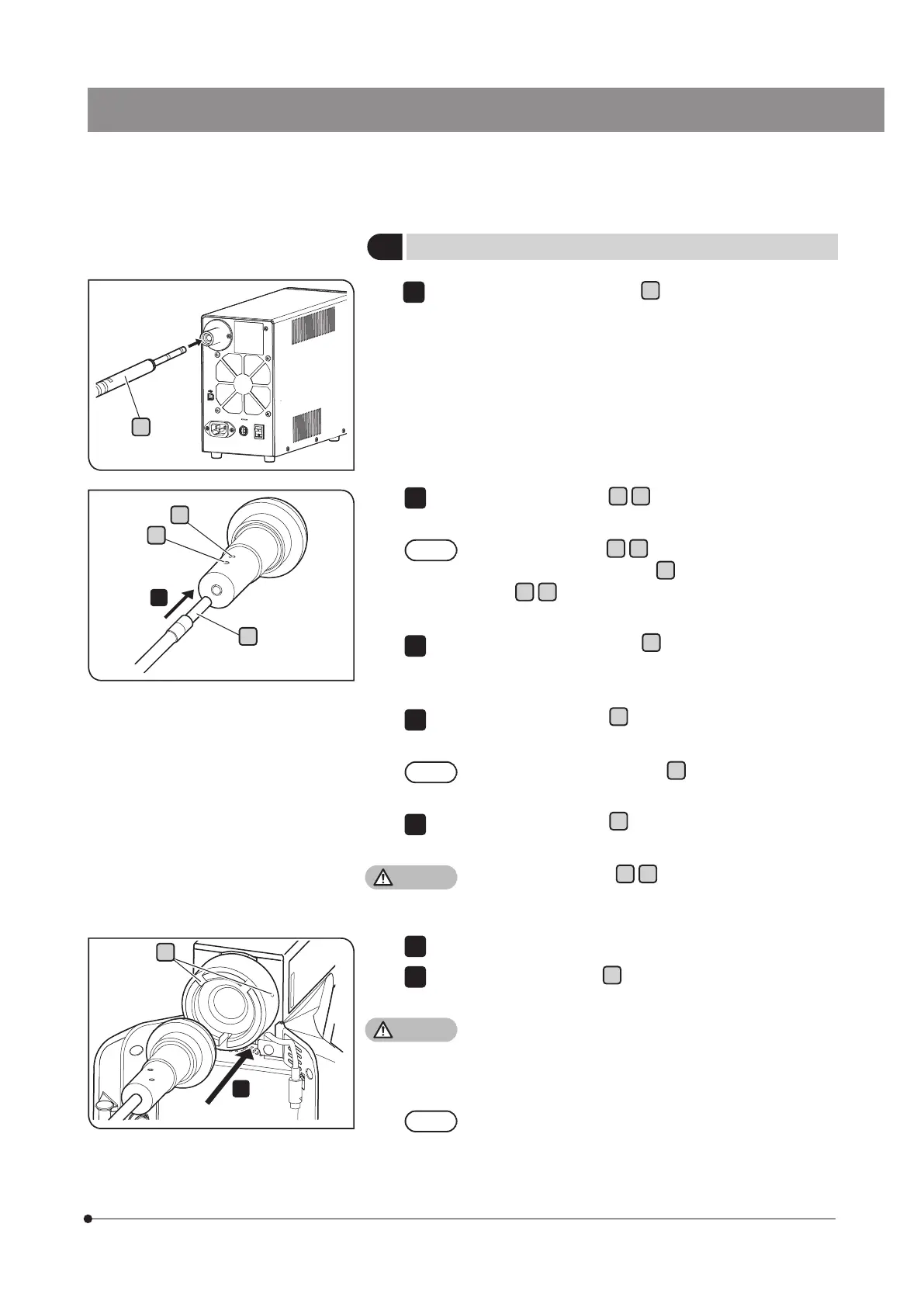
Loosen the clamping screws
B C
of U-LLGAD using the Allen
screwdriver provided with the microscope.
If the clamping screws
B C
are not fully loosened, the tip
of the emission side connector
D
contacts the clamping
screws
B C
and the emission side connector may not be
inserted to the correct position.
Insert the emission side connector
D
of U-LLG150/U-LLG300
completely to the end of the liquid light guide insertion port of
U-LLGAD.
Tighten the clamping screws
B
firmly using the Allen screwdriver
provided with the microscope.
Pull the emission side connector
D
toward you to make sure
that it does not come out.
Tighten the clamping screws
C
firmly using the Allen screwdriver
provided with the microscope.
If the clamping screws
B C
are not tightened firmly,
U-LLG150/U-LLG300 may come off from U-LLGAD and a
fire may be caused.
2
3
4
5
1
Attaching U-LLG150/U-LLG300
A
3
D
C
B
E
 Loading...