2.2 Rear Panel Connections
The rear panel connections are shown in Figures 2.2 and 2.3.
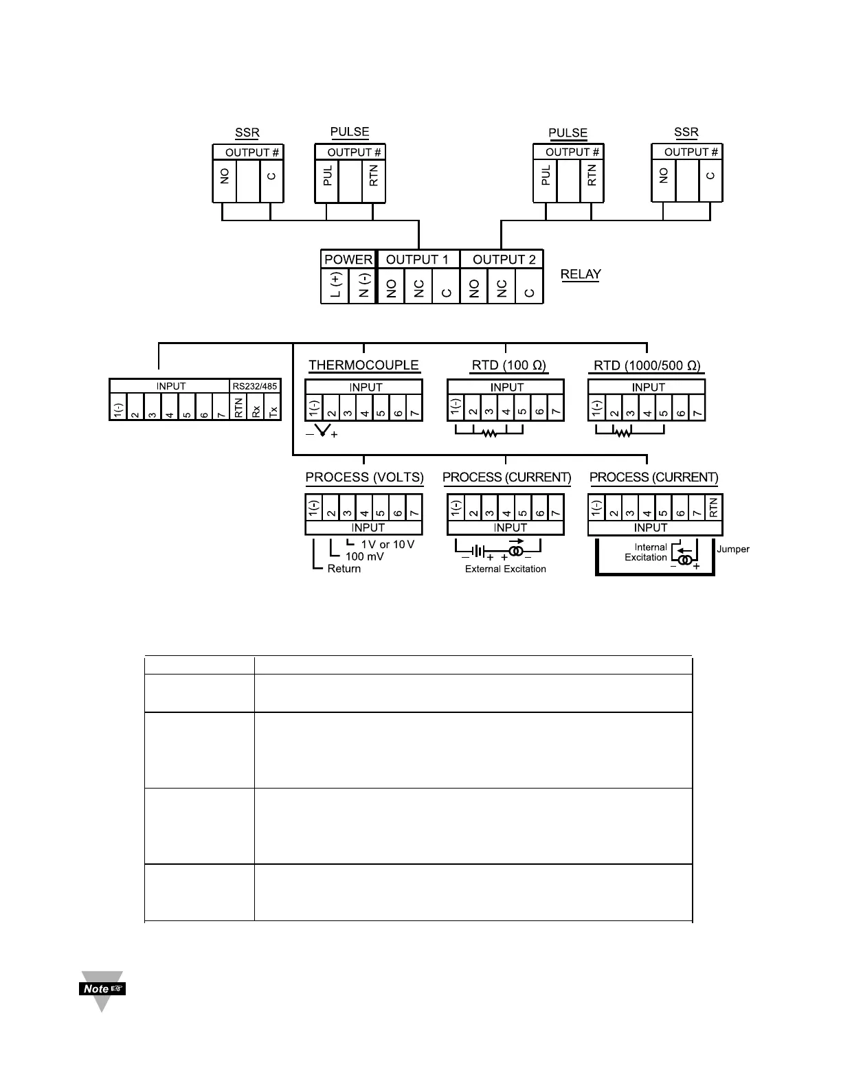
Figure 2.2 Rear Panel Power Connections
Figure 2.3 Rear Panel Input Connections
Table 2.2 Rear Panel Connector
POWER AC/DC Power Connector: All models
INPUT
Input Connector:
All models TC, PR (Process), RTD
OUTPUT 1 Based on one of the following models:
Relay SPDT
Solid State Relay
Pulse
OUTPUT 2 Based on one of the following models:
Relay SPDT
Solid State Relay
Pulse
OPTION
Based on one of the following models:
RS-232C or RS-485 programmable
Excitation
Output 1 and 2 are for -AL Limit Alarm Option only.