EasyManua.ls Logo

omi ED 18 - User Manual

omi ED 18
78 pages
Go to English
Print Icon
To Next Page IconTo Next Page
Loading...
OMI srl
OMI srlOMI srl
OMI srl
Cod. 710.0138.01.00 Rev1C – 09.2009
-
--
-
I
I I
I -
--
-
ESSICCATORI D’ARIA COMPRESSA AD ESPANSIONE DIRETTA
Manuale d’ uso e manutenzione
-
--
-
GB
GB GB
GB -
--
-
DIRECT EXPANSION COMPRESSED AIR DRYERS
Instruction and Maintenance Manual
-
--
-
D
D D
D -
--
-
DRUCKLUFT KÄLTETROCKNER
Handbuch für Betrieb und Wartung
-
--
-
F
F F
F -
--
-
SECHEUR D’AIR A EXPANSION DIRECTE
Manuel d’instructions et d’entretien
-
--
-
E
E E
E -
--
-
SECADORES A EXPANSIÓN DIRECTA
Manual de uso y mantenimiento
-
--
-
RUS
RUS RUS
RUS -
--
-
ОСУШИТЕЛИ СЖАТОГО ВОЗДУХА РАСШИРИТЕЛЬНОГО ТИПА
Руководство по эксплуатации и техническому обслуживанию
ED
18 – 24 – 54 – 72
108 – 144 – 180
270 – 360 – 480
660 – 780 – 1000

Table of Contents

Question and Answer IconNeed help?

Do you have a question about the omi ED 18 and is the answer not in the manual?

Summary

SYMBOLS AND SAFETY INFORMATION

Safety Symbols Guide

Highlights symbols indicating critical safety precautions and risks.

Operational Symbols Guide

Explains symbols related to air, condensate, and fan rotation.

1. GENERAL INFORMATION

1.1 Functional Description

Details the operational principles of the compressed air dryer.

1.2 Machine Safety Conditions

Outlines essential safety precautions for operating the equipment.

2. INSTALLATION

2.1 Acceptance and Transportation

Details procedures for receiving and moving the dryer.

2.2 Installation Site Requirements

Specifies environmental and location requirements for installation.

2.3 Installation Procedure

Covers the step-by-step process of physically installing the dryer.

3. START UP PROCEDURES

3.1 Control Panel Overview

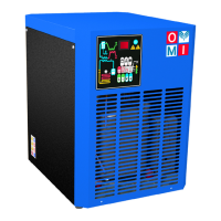
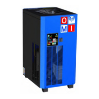
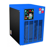
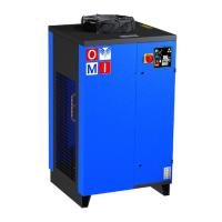
Describes the function and components of the dryer's control interface.

Display and LED Indicators

Explains display states and the meaning of signalling LEDs on the control panel.

3.1.1 Key Functions

3.1.2 Condensate Discharge Programming

3.1.3 Anomaly Warning System

Alarm Message Interpretation

Details specific error codes, their causes, system outputs, and recommended remedies.

3.1.4 Remote Signaling Alarm

3.2 Pre-Start Up Checks

3.3 Dryer Start Up

4. MAINTENANCE AND TROUBLESHOOTING

4.1 Maintenance Schedule

Details routine checks and upkeep procedures for the dryer based on operating hours.

4.2 Troubleshooting Common Issues

Lists common problems, their causes, and remedies, spanning multiple pages.

4.3 Dismantling Procedures

COMPONENT LEGEND

Component Identification Key

Lists and describes various parts of the dryer with their corresponding codes.

REFRIGERATION CIRCUIT DIAGRAMS

Models 18-480 Nm3;h Circuits

Shows the frigorific circuit for specific model ranges.

REFRIGERATION CIRCUIT DIAGRAMS (Model Range 660-1000 Nm3;h)

WIRING DIAGRAMS

230 V;1 Ph;50 Hz Models Wiring

Presents the wiring diagram for specific models and voltage.

230 V;1 Ph;60 Hz Models Wiring

Presents the wiring diagram for specific models and voltage.

WIRING DIAGRAMS (270-360 Nm3;h, 50 Hz)

WIRING DIAGRAMS (270 Nm3;h, 60 Hz)

WIRING DIAGRAMS (360 Nm3;h, 60 Hz)

WIRING DIAGRAMS (480 Nm3;h, 50 Hz)

WIRING DIAGRAMS (480 Nm3;h, 60 Hz)

WIRING DIAGRAMS (660 Nm3;h, 50 Hz)

POWER CIRCUIT DIAGRAMS

Models 780 & 1000 Nm3;h (400 V;3 Ph;50 Hz)

Details the power circuit for specific high-capacity models.

CONTROL CIRCUIT DIAGRAMS

Models 780 & 1000 Nm3;h Control

Details the control circuit for specific high-capacity models.

TECHNICAL DATA SHEET

Model Performance Specifications

Provides key performance and electrical data for each dryer model.

TECHNICAL DATA

Dimensional and Connection Data

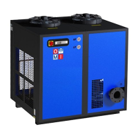
Shows dimensions and connection types for various dryer models.

DIMENSIONAL DATA

BASIC SPARE PARTS LIST

Spare Parts for Models 18-180 Nm3;h

Identifies spare parts for a range of dryer models.

BASIC SPARE PARTS LIST

Spare Parts for Models 270-480 Nm3;h

Identifies spare parts for specific high-capacity dryer models.

BASIC SPARE PARTS LIST

Spare Parts for Models 660-1000 Nm3;h

Identifies spare parts for specific high-capacity dryer models.

omi ED 18 Specifications

General IconGeneral
Dehumidification Capacity18 liters/day (30°C, 80% RH)
Tank Capacity2.5 liters
Operating Temperature Range5°C - 35°C
Dimensions330 x 210 x 500 mm
Weight10.5 kg

Related product manuals