AC/DC Current Clamp C-Probe 1
20
Note: Zero adjustment is also recommended in the following cases:
• prior to measuring very low currents (< 5 A)
• when successively measuring currents with different values
• at changed polarity.
Of course you can perform the DC adjustment directly at the
analog input the current clamp is connected to. For the
adjustment switch the input to the 100 mV measurement
range.
5.2 Current Measurement
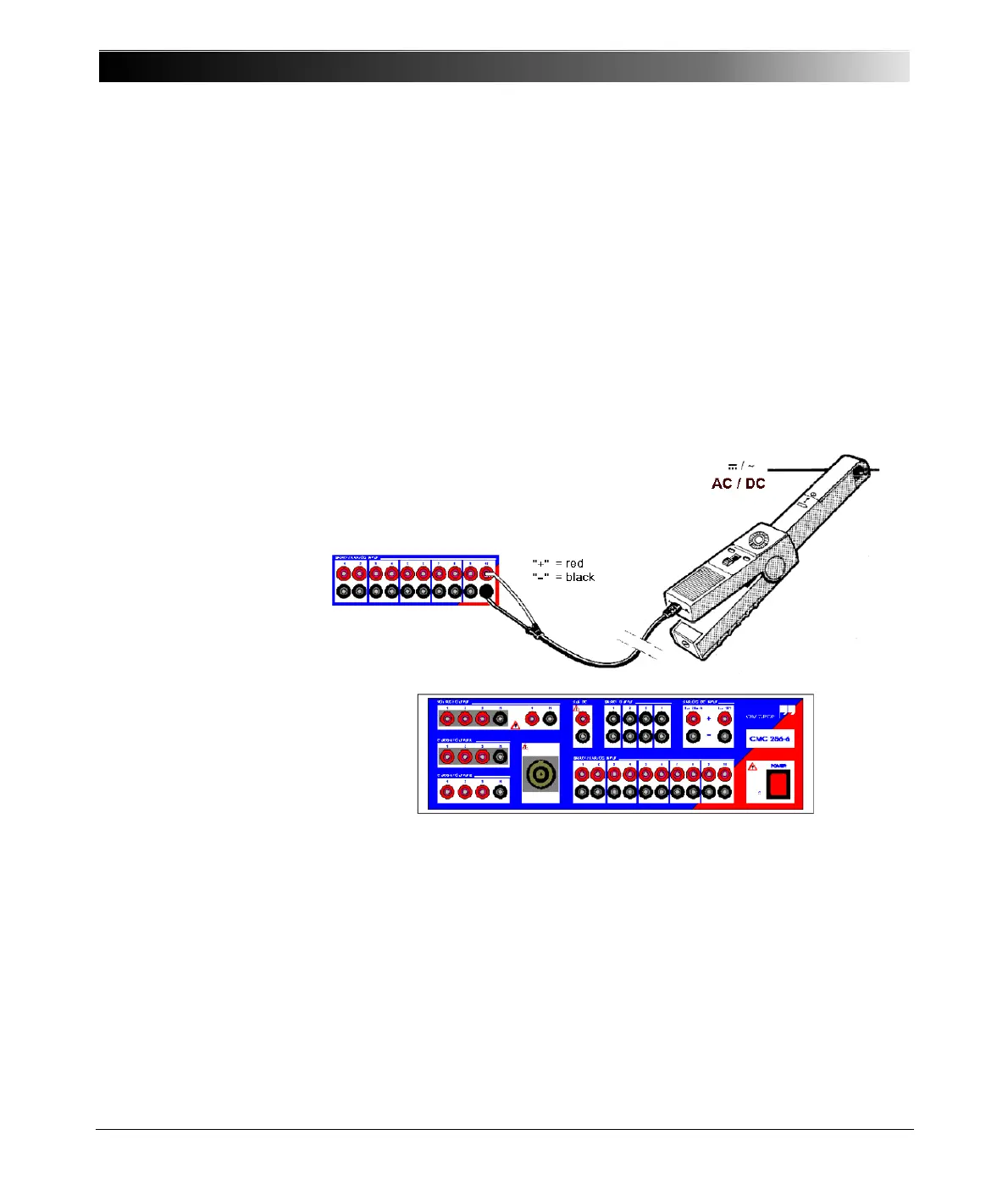
Figure 5-2:
Current measurement
1. Set the slide switch of C-Probe 1 to the desired measurement range of
100 mV/A or 10 mV/A. The control indicator "ON" lights up.
2. Perform a zero adjustment, if required (for example with the Analog DC
Input of the CMC 256 test set).
3. Connect C-Probe 1 to one of the analog outputs of the CMC 256 test set
(red = +, black = -).
4. Grasp the wire to be measured with the current clamp. The arrows on top
and underneath the clamp designate the current flow direction!
Make sure that the clamp jaws are clean and completely closed.