15
Setting Up the Test
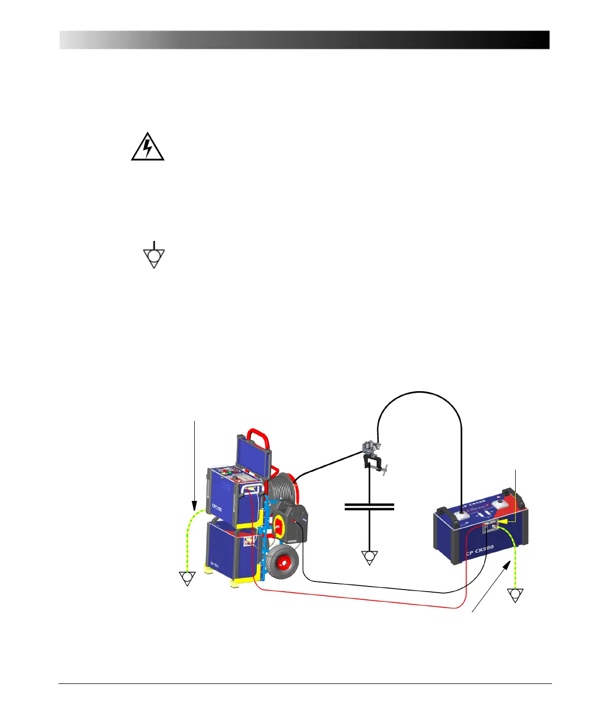
4.4 Connecting the CP CR500 to the Test Object
Caution:
– Never touch the high-voltage sockets of the CP CR500 during operation.
Consider these sockets as live, and due to the high voltage life-hazardous.
– The plugs of the high-voltage cables and the cables themselves are not
shielded and therefore not safe. While operating the CP CR500, consider
these cables as live, and due to the high voltage life-hazardous.
1. Connect the CP CR500's high-voltage cable to the test object (e.g., a
transformer) using the clamp provided with the CP CR500.
2. Connect low side of the test object to equipotential gound.
3. Connect the CP CR500's high-voltage cable to the high-voltage socket HV1
or HV2.
4. Connect the CP CR500's LV connector to CP TD1's connector IN A (red
plug) using the the low-voltage cable for measuring inputs.
5. Secure the CP CR500 unit with a chain or a barrier tape at a distance of at
least 1 m / 3 ft to prevent an accidental entering of the dangerous zone
during operation.
Figure 4-2:
Connecting the
CP CR500 to the test
object
--
HV Cable
CP TD1
HV Cable CP CR500
C
x
Clamp with sockets
*)
Note: This is not the OMICRON-supplied red
connecting cable. It is diplayed red here to denote
its importance for operational safety!
CPC 100
dongle
Grounding cable (yellow/green)
Grounding cable (yellow/green)
Safety
*)
 Loading...


