CP CR500
16
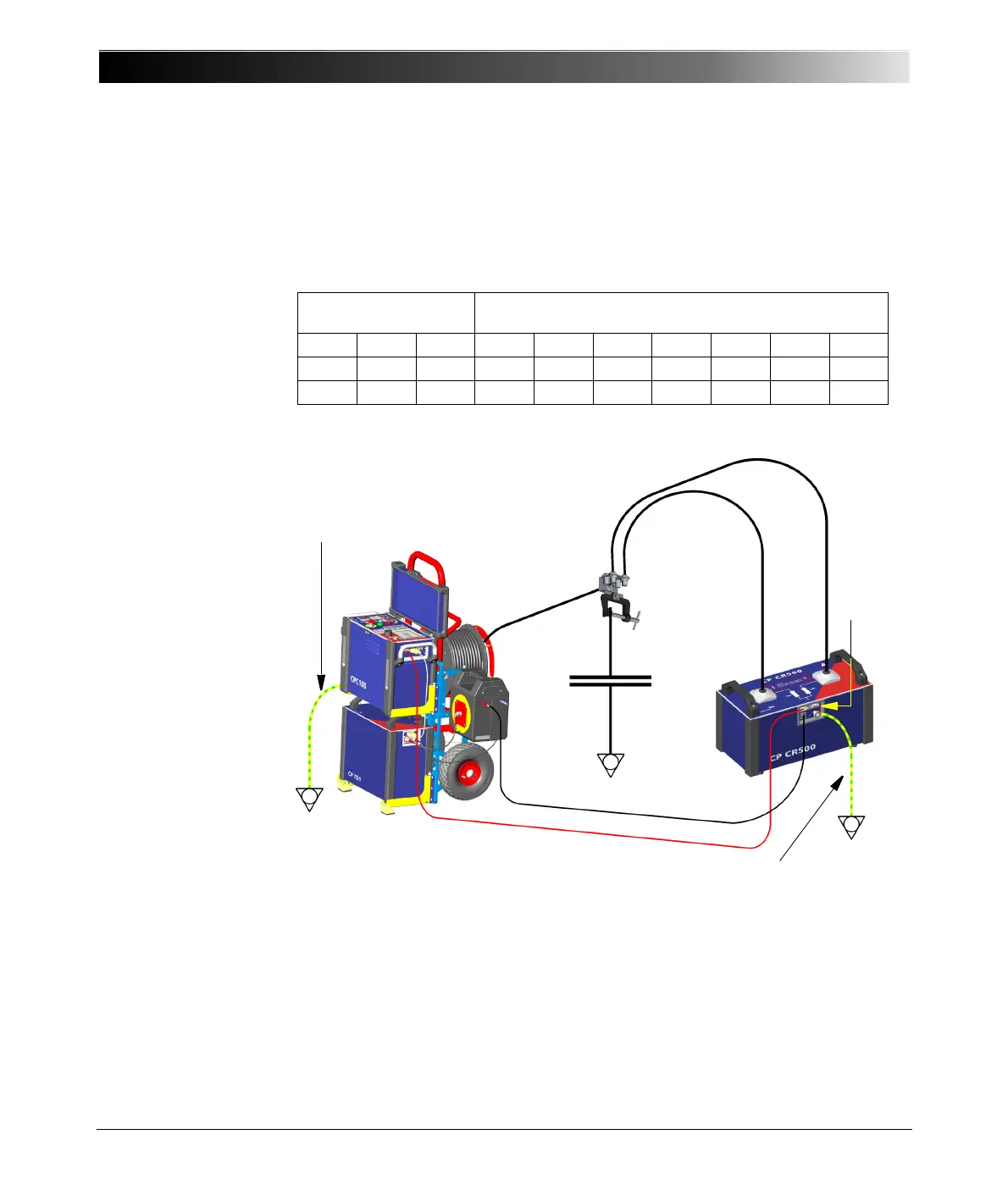
4.5 Connecting Both Inductors of a CP CR500
The CP CR500 contains two inductors with 40 H each. If one inductor alone
cannot compensate the designated capacity, a second inductor can be
connected in parallel.
Figure 4-3:
Using both CP CR500
inductors
4.6 Connecting Two CP CR500 Units in Parallel
To compensate larger capacities (> 500 nF) two CP CR500 units can be
connected in parallel. The following table shows all possible capacities to
compensate with different numbers of CP CR500.
Connection Configuration C-values [μF] and V
max
-values [kV]
at different resonance frequencies [Hz]
inductor L [H] I
max
[A]354250607185Hz
one 40.0 1.0 0.52/8.4 0.36/10 0.25/12 0.18/12 0.13/12 0.09/12 μF/kV
both 20.0 2.0 1.03/8.4 0.72/10 0.51/12 0.35/12 0.25/12 0.18/12 μF/kV
2 HV Cables CP CR500
Safety
*)
HV Cable
CP TD1
C
x
Clamp with sockets
CPC 100
dongle
Grounding cable (yellow/green)
Grounding cable (yellow/green)
*)
Note: This is not the OMICRON-supplied red
connecting cable. It is diplayed red here to denote
its importance for operational safety!
 Loading...


