17
Setting Up the Test
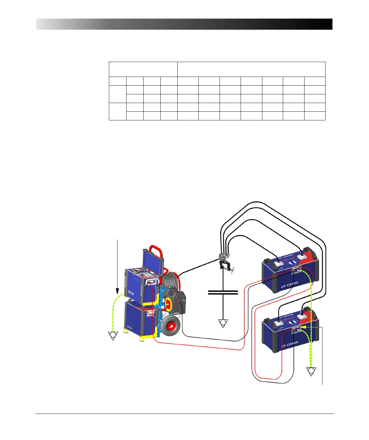
1. If you apply a second CP CR500 unit, connect it to the Safety B connector of
the first CP CR500 unit using the second modem-cable (length 9 m). Close
the Safety B connector on the second unit with the CPC 100 dongle.
2. Connect both CP CR500 units to the test object using the high-voltage
cables (4-4 ”Connecting two CP CR500 units in parallel”).
3. Connect both low-voltage LV connectors to each other using the delivered
standard connection leads 1 x 2 m x 2.5 mm² (black).
Figure 4-4:
Connecting two
CP CR500 units in
parallel
Connection Configuration C-values [μF] and V
max
-values [kV]
at different resonance frequencies [Hz]
# units # parll. L [H] I
max
[A]354250607185Hz
1 1 40.0 1.0 0.52/8.4 0.36/10 0.25/12 0.18/12 0.13/12 0.09/12 μF/kV
2 20.0 2.0 1.03/8.4 0.72/10 0.51/12 0.35/12 0.25/12 0.18/12 μF/kV
2 3 13.3 3.0 1.55/7.7 1.08/9.3 0.76/11 0.53/11 0.38/11 0.26/11 μF/kV
4 10.0 4.0 2.07/7.7 1.44/9.3 1.01/11 0.70/11 0.50/11 0.35/11 μF/kV
4 HV Cables CP CR500
Safety
*)
CPC 100 dongle
HV Cable
CP TD1
C
x
Clamp with
sockets
Grounding cable (yellow/green)
*)
Note: This is not the OMICRON-supplied red
connecting cable. It is diplayed red here to denote
its importance for operational safety!
 Loading...


