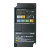
The following describes the Monitoring Signals. To put the Omron inverter in the ready to run
state whereby the unit is controlled by the ILE controller the MENU then ENTER buttons are
pressed. The monitoring section is entered by pressing the up arrow until you come to
FUNCTION U1 MONITOR then press the enter button to enter this mode.
U1-05 SPEED Displays the actual speed of the motor,
as calculated by the inverter. The speed
is displayed in Hz.
U1-02 FREQUENCY Displays the output frequency (Hz)
applied to the motor, as calculated by
the inverter.
U1-03 CURRENT Displays the motor current, as measured
by the inverter.
U1-09 TORQUE Displays the motor torque in per cent of
the rated motor torque, as calculated by
the inverter.
U1-08 POWER Displays the motor power.
U1-07 DC BUS VOLTAGE V Displays the DC bus voltage, as measured
in the inverter. The voltage is displayed
in Volts DC.
U1-06 OUTPUT VOLTAGE Displays the motor voltage, as
calculated by the inverter.
U1-13 OP HOUR COUNTER This Actual Signal is an elapsed-time
indicator. It counts the time the
inverter has a run command, and is not in a fault
state. The counted time cannot be reset.
U1-10 I/P Terminals Status of the digital inputs. If
the input is energised the display will
indicate 1. If the input is not
energised, the display will be 0.
U1-11 O/P STATUS Status of the three outputs. 1
indicates that the O/P is energised
and 0 indicates that the O/P is
de-energised.
 Loading...


