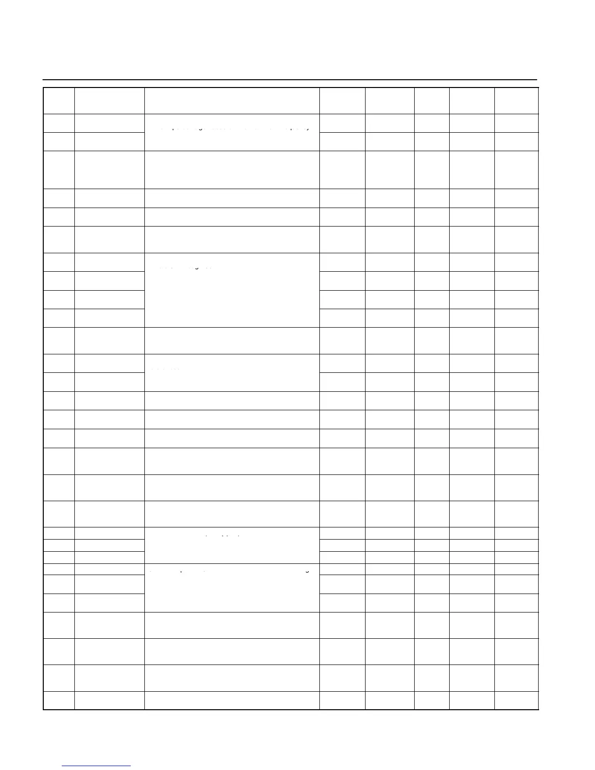
List of Parameters
12
Param-
eter
No.
Name Description Setting
range
Unit of
setting
(see note)
Default
setting
Changes
during op-
eration
Reference
page
n30 Frequency reference
upper limit
Used to set the upper and lower frequency reference
limits in percentage based on the maximum frequency
0 to 110 1% 100 No 16
n31 Frequency reference
lower limit
as 100%.
0 to 110 1% 0 No 16
n32 Rated motor current Used to set the rated motor current for motor overload
detection (OL1) based on the rated motor current.
Note Motor overload detection (OL1) is disabled by set-
ting the parameter to 0.0.
0.0 to 120%
of rated out-
put current
0.1 A Varies
with the
capacity.
No 16
n33 Motor protection
characteristics
Used to set the motor overload detection (OL1) for the
electronic thermal characteristics of the motor.
0 to 2 1 0 No 16
n34 Motor protective
time setting
Used to set the electric thermal characteristics of the
motor to be connected in 1-minute increments.
1 to 60 1 min 8 No 16
n35 Cooling fan opera-
tion function
Used to operate the Cooling Fan of the Inverter while
the Inverter is turned on or only while the Inverter is in
operation.
0, 1 1 0 No 16
n36 Multi-function input 1
(Input terminal S2)
Used to select the functions of multi-function input ter-
minals S2 through S5.
2 to 22 1 2 No 16
n37 Multi-function input 2
(Input terminal S3)
0 to 22 1 5 No 16
n38 Multi-function input 3
(Input terminal S4)
2 to 22 1 3 No 16
n39 Multi-function input 4 2 to 34 1 6 No 16
n40 Multi-function output
(MA/MB and MC
output terminals)
Used to select the functions of multi-function output
terminals.
0 to 7, 10 to
17
1 1 No 17
n41 Frequency reference
gain
Used to the input characteristics of analog frequency
references.
0 to 255 1% 100 Ye s 17
n42 Frequency reference
bias
–99 to 99 1% 0 Yes 17
n43 Analog frequency
reference filter time
Used to set the digital filter with a first-order lag for ana-
log frequency references to be input.
0.00 to 2.00 0.01 s 0.10 No 17
n44 Analog monitor
output
Used to set the output frequency or current as a moni-
tored item.
0, 1 1 0 No 17
n45 Analog monitor
output gain
Used to set the output characteristics of analog monitor
output.
0.00 to 2.00 0.01 1.00 Ye s 17
n46 Carrier frequency
selection
Used to set the carrier frequency. 1 to 4, 7 to
9
1 Varies
with the
capacity.
No 18
n47 Momentary power
interruption com-
pensation
Used to specify the processing that is performed when
a momentary power interruption occurs.
0 to 2 1 0 No 18
n48 Fault retry Used to set the number of times the Inverter is reset
and restarted automatically in the case the Inverter has
an overvoltage fault, overcurrent fault, or ground fault.
0 to 10 1 0 No 18
n49 Jump frequency 1
Used to set the frequency jump function.
0.0 to 400 0.1 Hz 0.0 No 18
n50 Jump frequency 2
qyjp
Note These values must satisfy the following condi
-
0.0 to 400 0.1 Hz 0.0 No 18
n51 Jump width
-
tion: n49 y n50
0.0 to 400 0.1 Hz 0.0 No 18
n52 DC control current
Used to impose DC on the induction motor for braking
0 to 100 1% 50 No 18
n53 Interruption DC
control time
control.
0.0 to 25.5 0.1 s 0.5 No 18
n54 Startup DC control
time
0.0 to 25.5 0.1 s 0.0 No 18
n55 Stall prevention
during deceleration
Used to select a function to change the deceleration
time of the motor automatically so that there will be no
overvoltage imposed on the motor during deceleration.
0, 1 1 0 No 18
n56 Stall prevention level
during acceleration
Used to select a function to stop the acceleration of the
motor automatically for stall prevention during
acceleration.
30 to 200 1% 170 No 19
n57 Stall prevention level
during operation
Used to select a function to reduce the output
frequency of the Inverter automatically for stall
prevention during operation.
30 to 200 1% 160 No 19
n58 Frequency detection
level
Used to set the frequency to be detected. 0.0 to 400 0.1 Hz 0.0 No 19
Note: Values longer than 3 digits are rounded up to the next unit multiple.