Function of Each Parameter
15
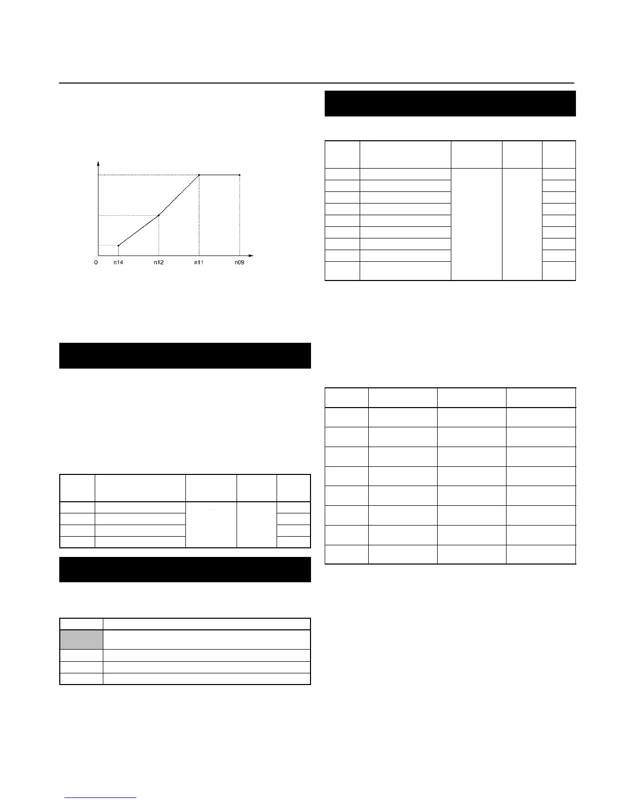
Note: For n09, n11, and n12, the unit of setting is as follows:
Values will be set in 0.1-Hz increments if the frequency is
less than 100 Hz and 1-Hz increments if the frequency is
100 Hz or greater.
Output
voltage (V)
Frequency
(Hz)
Note: 1. Set the parameters so that the following condition will
be satisfied.
n14 x n12 < n11 x n09
2. The value set in n13 will be ignored if parameters n14
and n12 are the same in value.
n10
n13
n15
Acceleration/Deceleration Time Settings
(n16 to n19)
The acceleration time is the time required to go from 0% to 100%
of the maximum frequency and the deceleration time is the time
required to go from 100% to 0% of the maximum frequency. The
actual acceleration or deceleration time is obtained from the fol-
lowing formula.
Acceleration/Deceleration time =
(Acceleration/Deceleration time set value) × (Frequency refer-
ence value) ÷ (Max. frequency)
Value Name Setting
range
Unit of
setting
Default
set-
tings
n16 Acceleration time 1
0.0 to 999 0.1 s
10.0
n17 Deceleration Time 1
10.0
n18 Acceleration time 2 10.0
n19 Deceleration Time 2 10.0
S-shape Acceleration/Deceleration Characteristic
(n20)
Any one of three S-shape acceleration/deceleration times (0.2,
0.5, and 1.0 s) is selectable.
Value Description
0 No S-shape acceleration/deceleration characteristic
(Trapezoidal acceleration/deceleration)
1 S-shape acceleration/deceleration characteristic time is 0.2 s
2 S-shape acceleration/deceleration characteristic time is 0.5 s
3 S-shape acceleration/deceleration characteristic time is 1.0 s
Note: When the S-shape acceleration/deceleration character-
istic time is set, the acceleration and deceleration times
will be lengthened according to the S-shape at the begin-
ning and end of acceleration/deceleration.
Setting the Frequency References 1 to 8 and the
Inching Frequency Command (n21 to n28 and n29)
Set internal frequency references.
Value Name Setting
range
Unit of
setting
Default
set-
tings
n21 Frequency reference 1
0.0 to max.
6.0
n22 Frequency reference 2
0.0
n23 Frequency reference 3
0.0
n24 Frequency reference 4 0.0
n25 Frequency reference 5 0.0
n26 Frequency reference 6 0.0
n27 Frequency reference 7 0.0
n28 Frequency reference 8 0.0
n29 Inching frequency com-
mand
6.0
Note: 1. Values will be set in 0.1-Hz increments if the frequency is less
than 100 Hz and 1-Hz increments if the frequency is 100 Hz
or over.
2. Frequency reference 1 is enabled with n03 for frequency ref-
erence selection set to 1. (Remote mode)
3. Frequency references 1 to 8 are enabled by setting multi-
step speed references 1, 2, and 3 in n36 to n39 for multi-func-
tion input. Refer to the following table for the relationship be-
tween multi-step speed references 1 to 3 and frequency ref-
erences 1 to 8.
Frequency
reference
Multi-step speed
reference 1
Multi-step speed
reference 2
Multi-step speed
reference 3
Frequency
reference 1
OFF OFF OFF
Frequency
reference 2
ON OFF OFF
Frequency
reference 3
OFF ON OFF
Frequency
reference 4
ON ON OFF
Frequency
reference 5
OFF OFF ON
Frequency
reference 6
ON OFF ON
Frequency
reference 7
OFF ON ON
Frequency
reference 8
ON ON ON
Note: 1. “ON” and “OFF” represent “input ON” and “input OFF,” re-
spectively.
2. Inching frequency commands take precedence over multi-
step speed references.