14
Note: The shaded values indicate default settings.
Parameter Write-prohibit Selection/Parameter
Initialization (n01)
This parameter makes it possible to write-prohibit parameters,
change the parameter set or displayed range, or initialize all pa-
rameters to default values.
Value Description
0 Only n01 can be displayed and set. The n02 through n79
parameters can be displayed only.
1 The n01 through n79 parameters can be displayed and set.
6 Only the error log memory is cleared.
8 Enables the initialization of all parameters in 2-wire sequence so
that the parameters will return to default values.
9 Enables the initialization of all parameters in 3-wire sequence.
Operation Mode Selection (n02)
Select the method of operation mode input to start or stop the In-
verter in remote mode.
Value Description
0 The RUN and STOP/RESET Keys of the Digital Operator are
enabled.
1 Multi-function input in 2- or 3-wire sequence through the control
circuit terminals is enabled.
Note: In local mode, RUN commands can be entered using the
Digital Operator only.
Frequency Reference Selection (n03)
(Remote Mode)
Select the method for inputting the frequency reference to the In-
verter in remote mode.
Value Description
0 The FREQ adjuster of the Digital Operator is enabled.
1 Frequency reference 1 (n21) is enabled.
2 The frequency reference control terminal (for 0- to 10-V input) is
enabled.
3 The frequency reference control terminal (for 4- to 20-mA current
input) is enabled.
4 The frequency reference control terminal (for 0- to 20-mA current
input) is enabled.
Interruption Mode Selection (n04)
Select the stopping method to be used when the STOP com-
mand is input.
Value Description
0 Frequency deceleration stop (Decelerates to stop in preset time.)
1 Free running (Output shut OFF by STOP command.)
Reverse Rotation-prohibit Selection (n05)
Select the operation to be performed when the reverse rotation
command is input.
Value Description
0 Reverse rotation possible (command accepted)
1 Reverse rotation prohibited (command not accepted)
STOP/RESET Key Function Selection (n06)
When parameter n02 is set to 1, set whether or not to use the
STOP/RESET Key of the Digital Operator to stop the Inverter in
remote mode. The STOP/RESET Key is always enabled in local
mode regardless of the setting in n02.
Value Description
0 The STOP/RESET Key of the Digital Operator is enabled.
1 The STOP/RESET Key of the Digital Operator is disabled.
Frequency Reference Selection (n07)
(Local Mode)
Select the input method of frequency references in local mode.
Value Description
0 The FREQ adjuster of the Digital Operator is enabled.
1 Key sequences on the Digital Operator are enabled.
Key Sequential Frequency Setting (n08)
Select whether to enable the Enter Key when setting the fre-
quency reference with the Increment and Decrement Keys on
the Digital Operator.
Value Description
0 The Enter Key is enabled. (The setting is made valid by pressing
the Enter Key.)
1 The Enter Key is disabled. (The setting is directly treated as a
frequency reference without the Enter Key being pressed.)
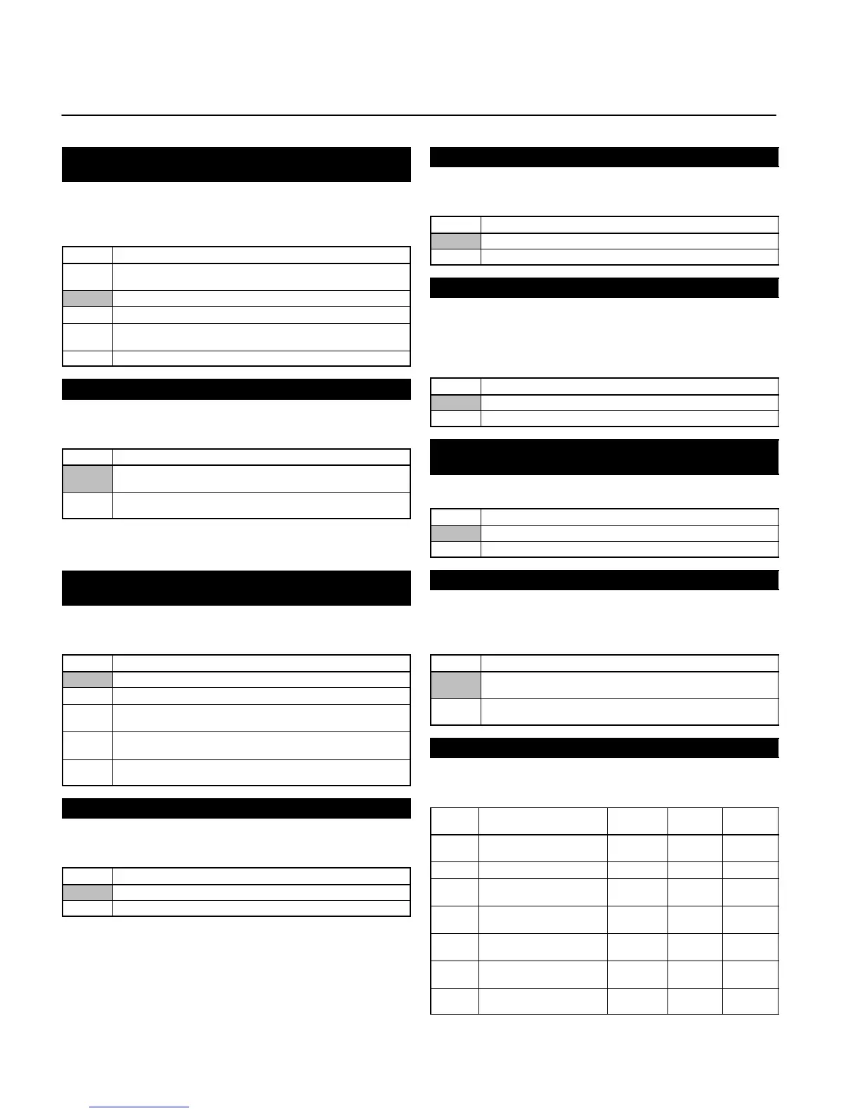
V/f Pattern Settings (n09 to n15)
Set the V/f pattern as the basic characteristic of the Inverter with
output voltage per frequency set.
Value Name Setting
range
Unit of
setting
Default
settings
n09 Maximum Frequency
(FMAX)
50.0 to 400 0.1 Hz 60.0
n10 Maximum Voltage (VMAX) 1 to 255 1 V 200
n11 Maximum Voltage
Frequency (FA)
0.2 to 400 0.1 Hz 60.0
n12 Middle Output Frequency
(FB)
0.1 to 399 0.1 Hz 1.5
n13 Middle Output Frequency
Voltage (VC)
1 to 255 1 V 12
n14 Minimum Output
Frequency (FMIN)
0.1 to 10.0 0.1 Hz 1.5
n15 Minimum Output
Frequency Voltage (VMIN)
1 to 50 1 V 12
Function of Each Parameter